Went for a blat today and noticed on the way back that the cooling fan wasn't cutting in as it is supposed to. On the climb up the hill to the house, the engine was getting perilously hot (well it was 104 fahrenheit out there). When I got home the fan still hadn't come on -the fuse had blown, again - it seems a 15A fuse isn't enough, but how much current can the wiring take? A question for Westfield methinks. In the meantime, I fitted a 30A fuse - if that blows we really have a problem. Mind you, we may have another altogether different problem if the wiring melts. Do not try this at home, I only used a 30A fuse because I didn't have a 20A one. This is a temporary measure.
On to Amazon (wonderful place). Ordered a lovely assortment of fuses for $8 and free shipping, to be delivered on Sunday, no less. I got 80 fuses for the price of 5 at AutoZone, give or take.
The engine was pinging a lot under load as well - modern engines aren't supposed to do that - but the Omex ECU doesn't use a knock sensor, so it doesn't know the engine is having problems. I suppose the UK set up doesn't take into account crappy US gas, temperatures over 100 degrees and nearly three thousand feet of altitude. I am guessing it is set up for sea level atmospherics and gloomy cold UK weather.
Worse still, it is a closed system, so I can't just go in and tweak it. To be discussed with Westfield when I am there next week. I am visiting the factory to return the assortment of extra brake pedals they supplied me with and other sundry bits and pieces I had left over, and to pick up my swirl pot, if it is ready, along with a couple of other missing items.
All that to say, there will be a lull in proceedings here while I wend my way, and back, to Blighty. . .
Friday, July 24, 2015
Thursday, July 23, 2015
Trunk/Boot locks and a mishap with the exhaust
Fitted the locks to the trunk (sorry, boot) today and what a faff that was - I drilled the holes for the locks on small marks on the trunk(boot)lid that are made during the fabrication process at the factory, and then used paint on the latches to locate where they entered the boot box, but no matter how big I made the slits, I couldn't get them to engage. No doubt this is in the manual, which I gave up on a long time ago, but the solution was:
Setting up my phone in the boot and taking a video when I shut the lid an operated the locks helped me see what was going on in there. Who's a clever boy then?
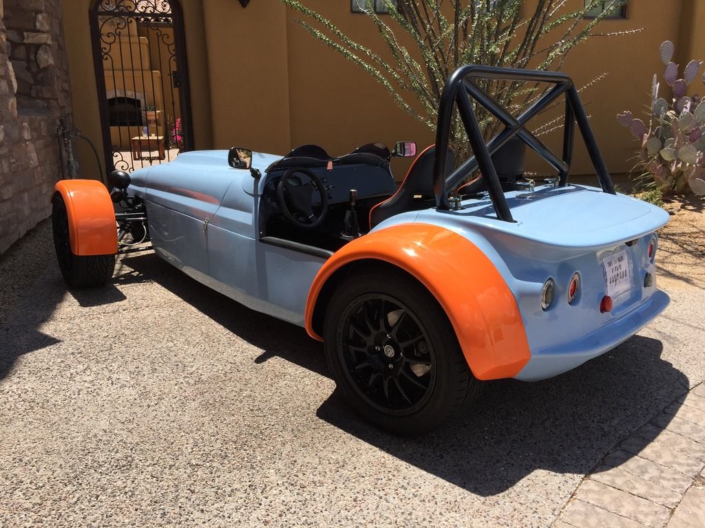
After all that and lots of trial and error, the boot lid finally locks. Both sets of keys are the same, so you actually end up with 3 spares! (perhaps I will keep one in the boot). In the photos below, you can see the damage to the boot lid caused in transit - I understand the replacement is on it's way, along with a new bonnet and rear wing.
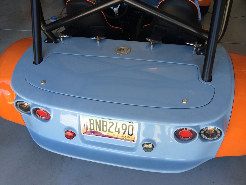
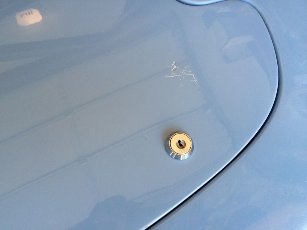
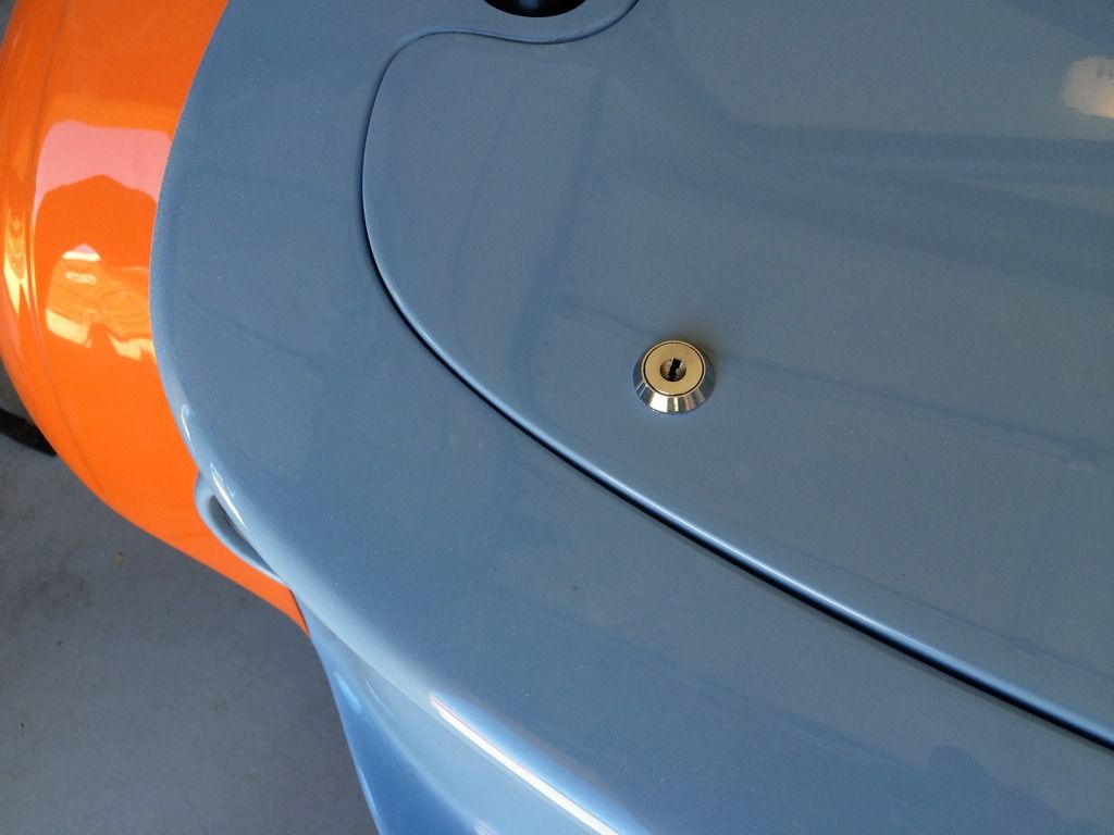
It is a neat job though - here is the other side:
Oh yes, and the catalytic converter fell off this morning - can't imagine how that happened!
 Much better. Doesn't look like a can of beans got such halfway any more!
On the subject of the exhaust, the headers are rapidly changing color. I suppose it was to be expected, but I wanted them nice and shiny at least for a little while. I guess it gets rather hot in there:

- flatten out each latch and rebend, as I realized the step in it was stopping the latch from rotating fully, as it was being stopped by the edge of the boot box. The bend is now closer to the lock mechanism than before.
- setting the latch so that it was not turned fully 90 degrees when locked (no need and it was fouling on the rear body panel - see next bullet)
- once the slit is cut in the bootbox I also needed to cut back the edge of the rear body panel, as in my case it was stopping the latch rotating. unfortunately that made a bit of a mess of the nice clean slits I had cut, but you don't see that handiwork unless the trunk, sorry boot, lid is off.
Setting up my phone in the boot and taking a video when I shut the lid an operated the locks helped me see what was going on in there. Who's a clever boy then?
After all that and lots of trial and error, the boot lid finally locks. Both sets of keys are the same, so you actually end up with 3 spares! (perhaps I will keep one in the boot). In the photos below, you can see the damage to the boot lid caused in transit - I understand the replacement is on it's way, along with a new bonnet and rear wing.
It is a neat job though - here is the other side:
Oh yes, and the catalytic converter fell off this morning - can't imagine how that happened!
On the subject of the exhaust, the headers are rapidly changing color. I suppose it was to be expected, but I wanted them nice and shiny at least for a little while. I guess it gets rather hot in there:
Tuesday, July 21, 2015
Fiddling with my Configuration
As the Westfield configuration wasn't correct for the oil pressure, and as I have checked the oil pressure with a mechanical gauge (hopefully that is right), I decided to change the configuration file manually - I had noted down readings at various RPM on the Dash2 and the mechanical gauge and determined that the Dash2 was fairly consistently out by a factor of 1.8, so using a laptop I reconfigured the scaling so it would read more sensible pressures. We will see how far off I am once I get the correct file from Westfield. While I was at it, I converted the reading from bar to psi (multiply by 14.503778, so what had been showing as 2.8 bar, now actually reads around 73 psi, which is in line with what I saw on the mechanical gauge and is about where it should be - perhaps a little low).
I also changed the scaling of the temperature gauge from centigrade to fahrenheit, and the gas tank from % remaining to US gallons (but I had to guess at the tank size of 45 litres - I have a feeling that is a little large, I think it may be closer to 30. Easy enough to fix once I get the confirmation from Westfield).
Was too hot to take Mr. Westfield out today - will take him to play tennis early in the morning. He will enjoy that.
Monday, July 20, 2015
So I Rushed out this Morning . . .
After tennis and went to the registration office to get a 3-day registration which allows you to take the car for inspection/registration/emissions testing etc. (and nothing else). I got there just after 9:00, and . . . they were closed, until 10:00. Bother. So I went home - stopping off at the hardware store on the way home to say hello and pick up a few large washers to put under the passenger side seat bolts to spread the load (Westfield still haven't sent them). Fitted them when I got home. I went back to the office later after they were open - the 3-day registration is simply a matter of handing over $6 to the charming lady there (really, so much nicer going through an independent agent rather than the DMV - you have to pay "convenience" fees, and in this case they really are - very convenient, no wait and service with a smile). So this was the result:
So a few final checks to ensure nothing was loose (especially the wheels, as one started to come off the Healey on my way to the inspection a year ago), grab my helmet and it's off we go. First stop the gas station, where I am stopped by a young man who said he just had to ask what it was. Turned out he was a photographer and he asked if he could take some pictures sometime - once I get the Gulf livery done (and the replacement body panels) I will take Mr. Westfield to see him.
On the subject of the body panels, I bonded some glassfibre to the underside of the bonnet where the cracks were to strengthen them. The cracks still show, but now the bonnet is solid and does not flex - gives a much better finish line with the nosecone.
I arrived at the inspection station around 1:50, and was immediately asked by someone if it was a Lotus. This car definitely attracts a lot of attention. Added my name to the list and was told the wait should only be half an hour or so. At 2:40 the inspector called me over and we got started. Fortunately, he was very helpful and it was a completely different experience I had had with the Healey with another inspector (which had filled me with some trepidation for Mr. Westfield).
The inspection process in Arizona is relatively straightforward - they just want to check the bills of sale (for the kit and the engine) and examine the serial numbers to ensure that nothing is stolen.
The serial number provided by Westfield isn't recognized by the system here so they assign an Arizona VIN number, which is attached to the chassis (and must not be tampered with). No real mechanical inspection needed (the inspector gave it the once over, I think more because he liked the look of it) and that was it - about a 20 minute process followed by some paperwork. After I explained what it was and showed him some pictures (which he said wasn't necessary), he agreed to title it as a replica of a 1960 Lotus 7. The title also shows it as a "Special Construction" which is Arizona speak for a kit car.
As it is titled as a 1960, the registration cost is only $10 a year and it is exempt from emissions testing (I think all special construction vehicles may be exempt, but I figured this route was the safest). I also believe that as a replica, I won't have a legal issue regarding the lack of a windshield and wipers, which are normally required - I think they were optional on the Lotus Seven. End result:
Legal!
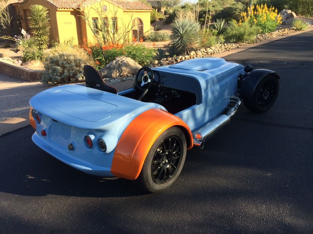
That view reminds me, I still have to fit the diffuser. Job 1 for tomorrow, or the next day.
The drive back was a lot of fun. What a car, and I haven't really pushed it yet.
 |
| Ready to go to see the inspector |
On the subject of the body panels, I bonded some glassfibre to the underside of the bonnet where the cracks were to strengthen them. The cracks still show, but now the bonnet is solid and does not flex - gives a much better finish line with the nosecone.
I arrived at the inspection station around 1:50, and was immediately asked by someone if it was a Lotus. This car definitely attracts a lot of attention. Added my name to the list and was told the wait should only be half an hour or so. At 2:40 the inspector called me over and we got started. Fortunately, he was very helpful and it was a completely different experience I had had with the Healey with another inspector (which had filled me with some trepidation for Mr. Westfield).
The inspection process in Arizona is relatively straightforward - they just want to check the bills of sale (for the kit and the engine) and examine the serial numbers to ensure that nothing is stolen.
 |
| In the inspection station. Turn your head and cough please |
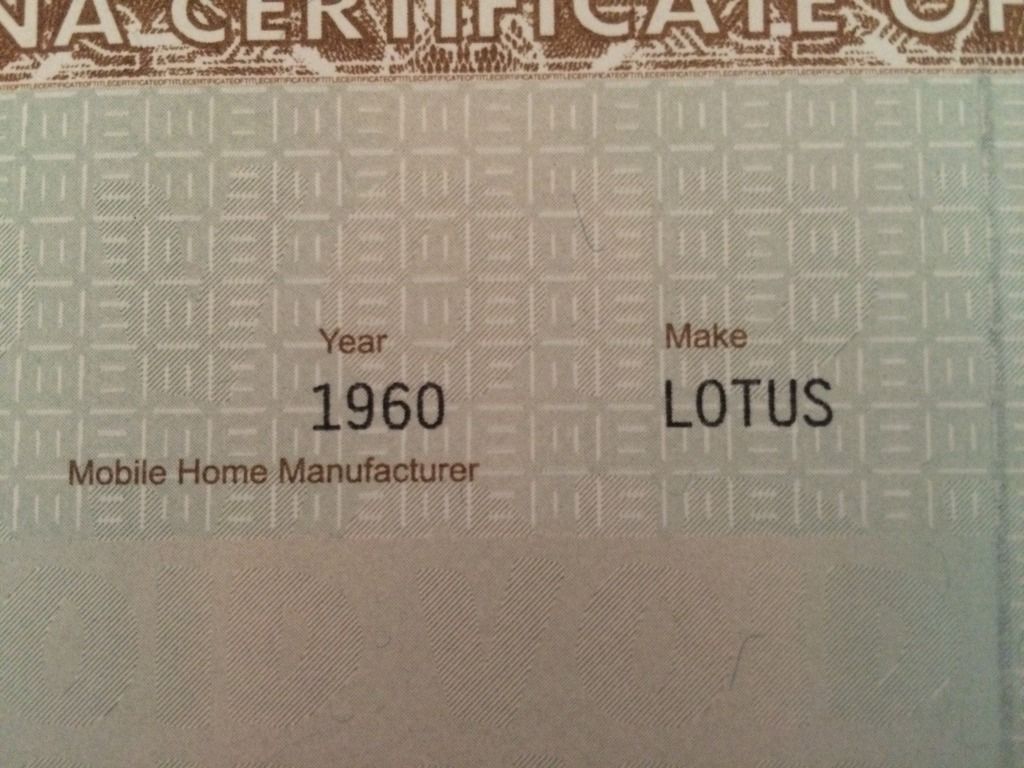 |
| A 1960 Lotus. Not sure why they think Lotus made mobile homes though |
As it is titled as a 1960, the registration cost is only $10 a year and it is exempt from emissions testing (I think all special construction vehicles may be exempt, but I figured this route was the safest). I also believe that as a replica, I won't have a legal issue regarding the lack of a windshield and wipers, which are normally required - I think they were optional on the Lotus Seven. End result:
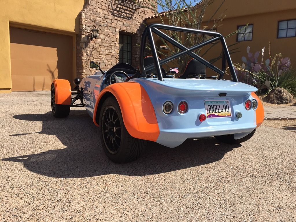 |
| Finally, we can go for a spin legally! |
That view reminds me, I still have to fit the diffuser. Job 1 for tomorrow, or the next day.
The drive back was a lot of fun. What a car, and I haven't really pushed it yet.
Sunday, July 19, 2015
Back from the Mountains
Back from the Rockies and on with a bunch of small remaining items.
I adjusted the ride height so that I wouldn't keep scraping the gearbox mount on my driveway - I set it slightly lower than the recommended 140mm at the front and 165 mm at the rear (135/155 measured under the chassis rails, after putting weight in the driver's seat/footwell to approximate to my weight when dressed with a helmet etc.). No scraping on the driveway any more! I need to make a camber gauge, so in the meantime I did an approximate setting using a spirit level on the wheels, which showed a small amount of negative camber on each wheel. There is still too much toe-in at the front, but it will do for the time being until I can get it to a shop that can set everything up accurately. The recommended settings from Westfield are shown below:
I also decided to tackle the gear knob - as other Mega S2000 owners have noted the Westfield gear knob is too large for the Honda gearstick - I addressed this by winding on three nuts to the gearstick then grinding them down until the gear knob would just fit over - I could then attach it securely with the three grub screws. It fits very securely with no wobble that I was fearing.
I was going to cut the gear stick down, as it seemed quite long, but I actually find it is a good height as it is, with your arm resting on the handbrake lever. I also fitted the provided gaiter as best I could, but I am not really satisfied with the outcome - I will have to come up with another solution (it is a little short, and untidy at the bottom):
The handbrake gaiter fit much better. I had struggled with this before, but came up with the solution of stapling the gaiter to the rectangular rubber seal that goes over the handbrake, then securing with the metal bracket. A little untidy, and it wouldn't show if I was fitting carpets, but this being a track car I am not. Anyway, it is functional. There are that many screws because there were that many holes!
I also fitted the VDO temperature sender, which should look like this:
 A strange type of connector that I have not seen before, but a female spade connector fits on it sideways.
This gave much more sensible temperature readings, with the fan cutting in around 94 C.
I also removed the oil pressure sender and fitted a mechanical gauge to check the oil pressure. The Dash2 was reading 0.5 bar on idle when hot and a maximum pressure of 2.8 bar when driven. I felt this was just way too low and the mechanical gauge agreed, showing just over 1 bar on idle and between 5 and 6 bar when revved (you could see the impact of the pressure relief valve dropping the pressure to around 5 bar after being momentarily higher).
I got a revised configuration file from Westfield, but that gave nonsensical oil pressure readings, so I am waiting for another file.
All being well, I should be able to take Mr. Westfield to the DMV tomorrow for show and tell.
I adjusted the ride height so that I wouldn't keep scraping the gearbox mount on my driveway - I set it slightly lower than the recommended 140mm at the front and 165 mm at the rear (135/155 measured under the chassis rails, after putting weight in the driver's seat/footwell to approximate to my weight when dressed with a helmet etc.). No scraping on the driveway any more! I need to make a camber gauge, so in the meantime I did an approximate setting using a spirit level on the wheels, which showed a small amount of negative camber on each wheel. There is still too much toe-in at the front, but it will do for the time being until I can get it to a shop that can set everything up accurately. The recommended settings from Westfield are shown below:
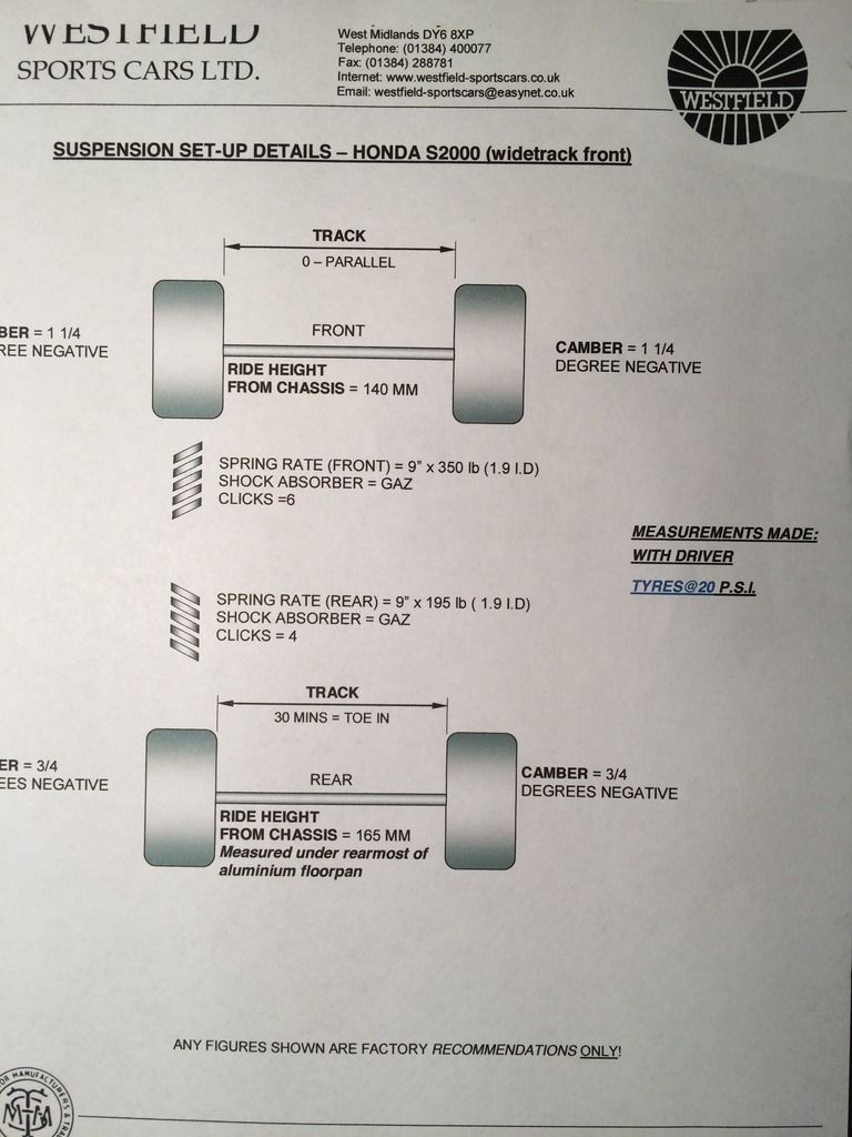 |
| Suspension set up direct from the factory |
I was going to cut the gear stick down, as it seemed quite long, but I actually find it is a good height as it is, with your arm resting on the handbrake lever. I also fitted the provided gaiter as best I could, but I am not really satisfied with the outcome - I will have to come up with another solution (it is a little short, and untidy at the bottom):
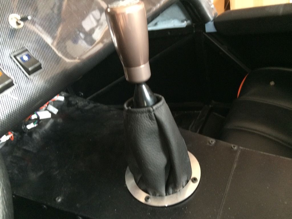 |
| Funny little gear gaiter |
The handbrake gaiter fit much better. I had struggled with this before, but came up with the solution of stapling the gaiter to the rectangular rubber seal that goes over the handbrake, then securing with the metal bracket. A little untidy, and it wouldn't show if I was fitting carpets, but this being a track car I am not. Anyway, it is functional. There are that many screws because there were that many holes!
 |
| Handbrake is neater than the gearstick |
I also fitted the VDO temperature sender, which should look like this:
This gave much more sensible temperature readings, with the fan cutting in around 94 C.
I also removed the oil pressure sender and fitted a mechanical gauge to check the oil pressure. The Dash2 was reading 0.5 bar on idle when hot and a maximum pressure of 2.8 bar when driven. I felt this was just way too low and the mechanical gauge agreed, showing just over 1 bar on idle and between 5 and 6 bar when revved (you could see the impact of the pressure relief valve dropping the pressure to around 5 bar after being momentarily higher).
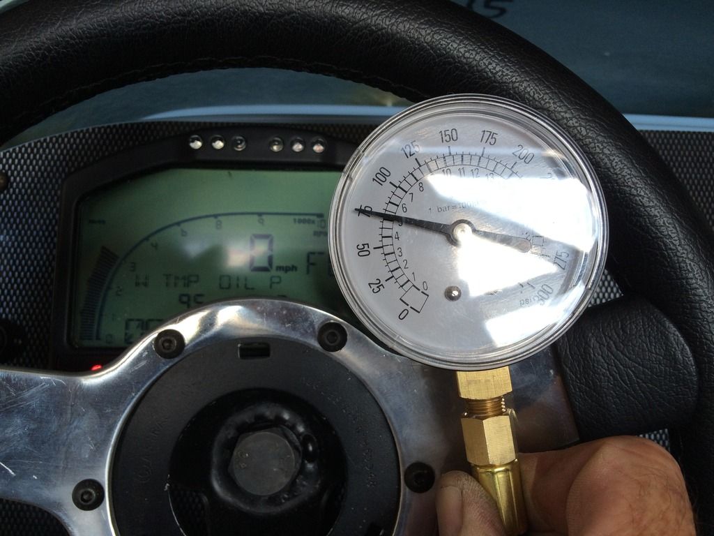 |
| 5 bar (75 psi) at 3,000 RPM, now that's more like it! |
I got a revised configuration file from Westfield, but that gave nonsensical oil pressure readings, so I am waiting for another file.
All being well, I should be able to take Mr. Westfield to the DMV tomorrow for show and tell.
Friday, July 10, 2015
Final Jobs
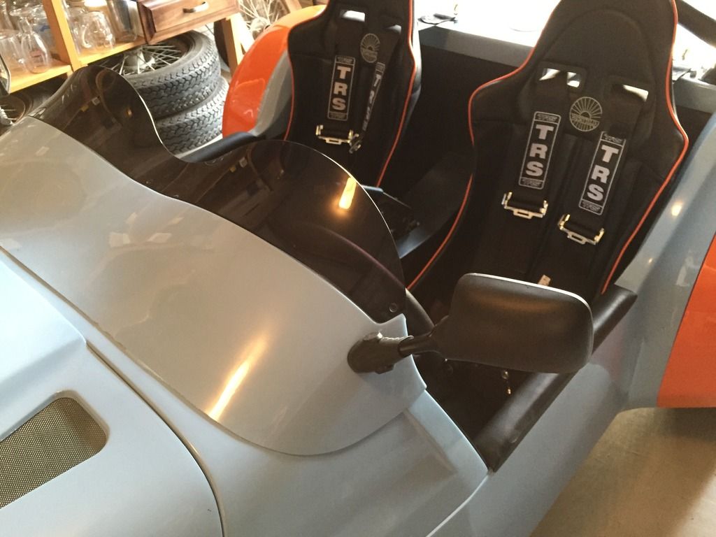
I received the spacers for the harness eyelets yesterday so I fitted them today. I was able to do it without removing the rollbar, which was a nice surprise. It is, however, impossible to enlarge the holes unless you have the flexible drive attachment for the Dremel. With that it took about 15 minutes to do all four. I did have to grind down the rollbar mount slightly on the right hand side to get the spacer to fit - other than that no problem, and I was able to get all four to tighten up nice and straight:
The harnesses attached very easily to the lower mounting points - no problems with powdercoating in the threads. Here is the final product:
I have not fitted the crotch straps yet as I am still waiting for the hardware. Actually getting into the race seat and attaching the harness is quite a faff unless you have a pit crew!
After that, the final, and yes I mean final, job was to hook up the speedometer sensor and calibrate the dash. After a bit of adjusting of the position of the sender, it worked fine - it even told me (accurately) what gear I was in! Actually a bit fiddly to enter the calibration on the dash but I got it eventually (after not hitting the enter button the first time).
I say it was the final job, but it really isn't. Westfield sent me a replacement temperature sender, but I can't use it because it has a funky wiring attachment - I have never seen one like that before. I also still need to tidy away/attach the wiring under the dash, and of course do the geo set up. And then there is the phantom swirl pot, the replacement body panels and the side impact bars than need a little modification.
I went to the DMV to see if I could get a temporary registration - no luck. The best they could do for me was a three-day registration so I could take Mr. Westfield down there so he could have a level II inspection (I think they stick a finger in his exhaust and ask him to cough). That was no use to me as I am away next week. Will sort it out when I get back. I just know it will be a headache.
These did arrive today though:
They will work a lot better on the track than the (wrong) tyres that were sent with the kit. I have run a set of R888s on my Lotus recently, and while they are an OK track tyre they don't let go progressively - it is all or nothing. We will see how they fare on the lighter Westfield.
Finally, a shot of Mr. Westfield's wonky mirror. I am not sure if it is annoying me enough yet to take it off and adjust it:
From that angle, it looks fine.
Oh, and by the way, don't stand too close to the exhaust on a Westfield. Ask me how I know:
Signing off for a week's vacation in Colorado. Will update with the progress with the DMV when I get back!
I still can't get the time-lapse video off my computer and on to YouTube. That is another thing that will have to wait until I get back.
 |
| Harness spacers fitted and ready to go |
The harnesses attached very easily to the lower mounting points - no problems with powdercoating in the threads. Here is the final product:
 |
| Faff city - no popping down the road with these boys to put on - it takes at least 15 minutes to get strapped in! |
I have not fitted the crotch straps yet as I am still waiting for the hardware. Actually getting into the race seat and attaching the harness is quite a faff unless you have a pit crew!
After that, the final, and yes I mean final, job was to hook up the speedometer sensor and calibrate the dash. After a bit of adjusting of the position of the sender, it worked fine - it even told me (accurately) what gear I was in! Actually a bit fiddly to enter the calibration on the dash but I got it eventually (after not hitting the enter button the first time).
I say it was the final job, but it really isn't. Westfield sent me a replacement temperature sender, but I can't use it because it has a funky wiring attachment - I have never seen one like that before. I also still need to tidy away/attach the wiring under the dash, and of course do the geo set up. And then there is the phantom swirl pot, the replacement body panels and the side impact bars than need a little modification.
I went to the DMV to see if I could get a temporary registration - no luck. The best they could do for me was a three-day registration so I could take Mr. Westfield down there so he could have a level II inspection (I think they stick a finger in his exhaust and ask him to cough). That was no use to me as I am away next week. Will sort it out when I get back. I just know it will be a headache.
These did arrive today though:
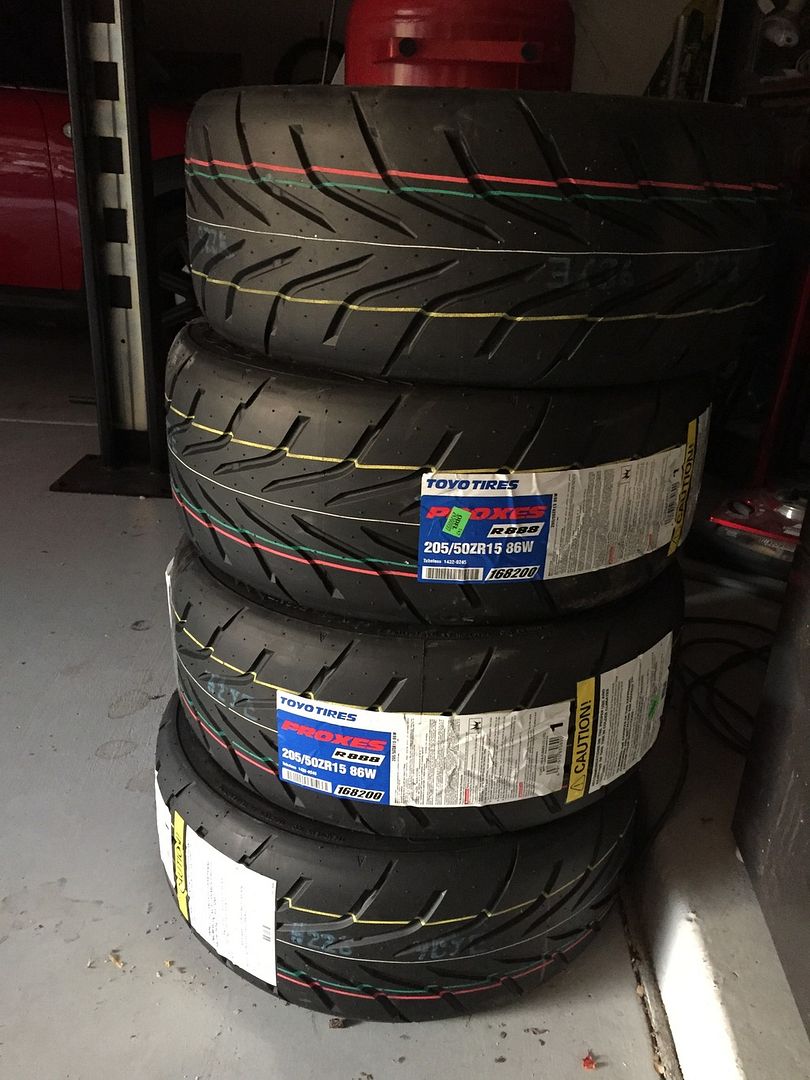 |
| Some real track tyres |
They will work a lot better on the track than the (wrong) tyres that were sent with the kit. I have run a set of R888s on my Lotus recently, and while they are an OK track tyre they don't let go progressively - it is all or nothing. We will see how they fare on the lighter Westfield.
Finally, a shot of Mr. Westfield's wonky mirror. I am not sure if it is annoying me enough yet to take it off and adjust it:
From that angle, it looks fine.
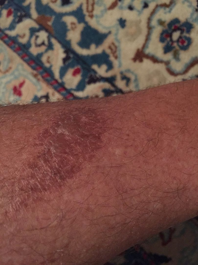 |
| Nice calf burn from a hot exhaust. Thankfully, the exhaust is not on the driver's side! |
Signing off for a week's vacation in Colorado. Will update with the progress with the DMV when I get back!
I still can't get the time-lapse video off my computer and on to YouTube. That is another thing that will have to wait until I get back.
Thursday, July 9, 2015
Aeroscreen
This is a job I had really been putting off, to be honest, as trying to get the holes lined up seemed to be a daunting task. As it was, it really wasn't that bad.
Siting the middle three holes was done by eye (as they are not precisely bonded to the underside of the aeroscreen. the front of the aeroscreen ended up being around 20 mm from the front of the scuttle I actually worked to ensure that the middle screw holding on the perspex screen was more or less directly above the middle dash fixing screw (as this holds the aluminum support bracket - it actually didn't end up directly above, but a little bending of the bracket helped). Drilling the holes oversize helped with locating the aeroscreen. I ensured the front of the aeroscreen was parallel with the front of the scuttle.
I don't know if I was lucky, but the side bolts were easy to locate - I just made sure the front of the aeroscreen overlapped the dash at the sides - I was able to mark where the shortened bolts were touching the scuttle and drilled oversize holes there - no need for slotted holes - the aeroscreen is flexible enough to work the bolts through with a little bending.
The only thing I am a little concerned about is the bolts go through the scuttle at an angle - I put large washers on the back prior to tightening the nylock nuts, but I am wondering if there should be some spacers in there to take the load. I am also wondering if there should be a finishing strip to the front of the aeroscreen to stop it chafing, to seal the gap and to make it a little neater - the front of mine is quite rough (I have been on to Westfield about this, we will see what they say).
Finally, I fit the wing mirrors. Unfortunately, fitting is a little hit and miss (I was basing the placement on pictures I had taken of the demo car last year at the factory) and after fitting the driver's side, I found that I couldn't get the body of the mirror parallel to the ground (it points up in the air a little). With experimentation, I was able to get the passenger side level by making the front mounting hole a little higher. The driver's side will come off at some point for hole adjustment.
So I went out for a little blat to test the aeroscreen and mirrors. The screen works well, but with the lowered floors, I am sitting too low - I had thought putting the runners in would be sufficient to raise the seats enough, but apparently not. I had omitted the spacers, so I will put them in to see how much of a difference that makes, but I think the seat needs to be at least an inch higher - I found myself peering around it.
I have found the car to be very low, or our driveway very steep. if I don't go out at an angle, the hoop under the gearbox smacks the ground at the top of the driveway - I took a look underneath yesterday and it is already in a very bad way - Fortunately I can raise the ride height by adjusting the springs - perhaps I should do that while it is being used on the road (as opposed to the track). Another job for tomorrow.
Finally. . .
The spacers for the harnesses eyelets arrived by airmail today (but still no swirl pot) so I can fit them tomorrow and hopefully go to the DMV. Fingers crossed! I do still have to wire in the speedo sensor and do something with the mass of wires under the dash, most of which are not used. I could just cut a lot of them out, but I want to keep them just in case I do want to turn Mr. Westfield into a road-going car at some point.
Have been trying to upload the complete time-lapse video but with no luck - watch this space!
 |
| First three holes made by eye. Actually with a drill, as I don't have laser beams for eyes, but you know what I mean |
I don't know if I was lucky, but the side bolts were easy to locate - I just made sure the front of the aeroscreen overlapped the dash at the sides - I was able to mark where the shortened bolts were touching the scuttle and drilled oversize holes there - no need for slotted holes - the aeroscreen is flexible enough to work the bolts through with a little bending.
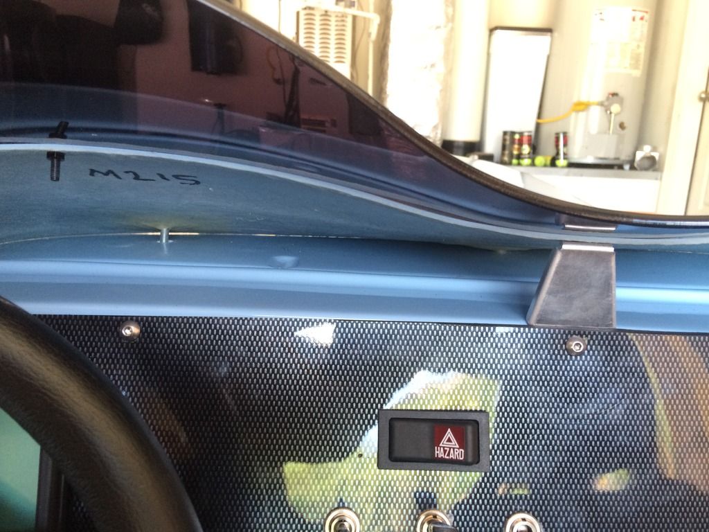 |
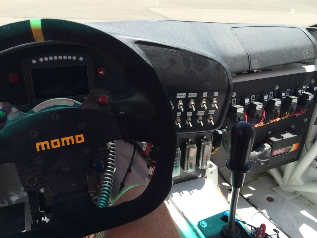
| view from the cockpit |
The only thing I am a little concerned about is the bolts go through the scuttle at an angle - I put large washers on the back prior to tightening the nylock nuts, but I am wondering if there should be some spacers in there to take the load. I am also wondering if there should be a finishing strip to the front of the aeroscreen to stop it chafing, to seal the gap and to make it a little neater - the front of mine is quite rough (I have been on to Westfield about this, we will see what they say).
 |
| Finished aeroscreen |
 |
| . . .abd from the other side |
Finally, I fit the wing mirrors. Unfortunately, fitting is a little hit and miss (I was basing the placement on pictures I had taken of the demo car last year at the factory) and after fitting the driver's side, I found that I couldn't get the body of the mirror parallel to the ground (it points up in the air a little). With experimentation, I was able to get the passenger side level by making the front mounting hole a little higher. The driver's side will come off at some point for hole adjustment.
So I went out for a little blat to test the aeroscreen and mirrors. The screen works well, but with the lowered floors, I am sitting too low - I had thought putting the runners in would be sufficient to raise the seats enough, but apparently not. I had omitted the spacers, so I will put them in to see how much of a difference that makes, but I think the seat needs to be at least an inch higher - I found myself peering around it.
I have found the car to be very low, or our driveway very steep. if I don't go out at an angle, the hoop under the gearbox smacks the ground at the top of the driveway - I took a look underneath yesterday and it is already in a very bad way - Fortunately I can raise the ride height by adjusting the springs - perhaps I should do that while it is being used on the road (as opposed to the track). Another job for tomorrow.
Finally. . .
The spacers for the harnesses eyelets arrived by airmail today (but still no swirl pot) so I can fit them tomorrow and hopefully go to the DMV. Fingers crossed! I do still have to wire in the speedo sensor and do something with the mass of wires under the dash, most of which are not used. I could just cut a lot of them out, but I want to keep them just in case I do want to turn Mr. Westfield into a road-going car at some point.
Have been trying to upload the complete time-lapse video but with no luck - watch this space!
Wednesday, July 8, 2015
Bonnet latches, cycle wings and grill
Bonnet latches
Also straightforward, I found that the centerlines for the rivets on the two halves of the mechanism should be 53 mm apart for a good solid clasp (found by trial and error prior to attaching to the body).
No access to the rear for the bottom half, so no way to add spreader washers, hopefully the fact that it has three rivets will spread the load a little.
GRP cycle wings
Bonded the big head bolts to the underside of the grip cycle wings. I shortened them as much as I could beforehand (when bolted on with nyloc nuts there are no threads showing, so hopefully they will be secure). The steps were:
Refitting the wheels was a bit of a struggle, as the grp wings seem to be a bit narrower than the carbon effect ones and the sides come down a bit further, so it was quite a tight fit. I had to bend the brackets out slightly so they didn't rub.
Grill (or is it grille?)
While I was working with the glassfibre, I bonded in some tie downs I made from electrical wire into the nose, so I could have an invisible fitting to the grill.
It really gives a very neat finish compared to the factory approach of drilling holes in the nose and threading tie-wraps through. The grill was secured with four tie-wraps from the inside.
Also straightforward, I found that the centerlines for the rivets on the two halves of the mechanism should be 53 mm apart for a good solid clasp (found by trial and error prior to attaching to the body).
 |
| marking up for the latches. More holes in the bodywork |
No access to the rear for the bottom half, so no way to add spreader washers, hopefully the fact that it has three rivets will spread the load a little.
GRP cycle wings
Bonded the big head bolts to the underside of the grip cycle wings. I shortened them as much as I could beforehand (when bolted on with nyloc nuts there are no threads showing, so hopefully they will be secure). The steps were:
- Enlarge holes in brackets
- cover brackets with saran wrap/cling film to stop the bolts sticking to them
- insert big heads in holes, apply JB Weld (epoxy) and fit cycle wings, measuring from the front of each wing to the first bracket to ensure they were the same (200mm in my case)
- Wait overnight for the epoxy to really set up then wrestle off the cycle wings. Although not as flexible as the carbon effect jobbies, there is still enough flexibility (with the enlarged holes and shortened bolts) to remove them (pulling the rear bracket forward a little bit also helps). I found it easiest to get the fronts out first, followed by the rears.
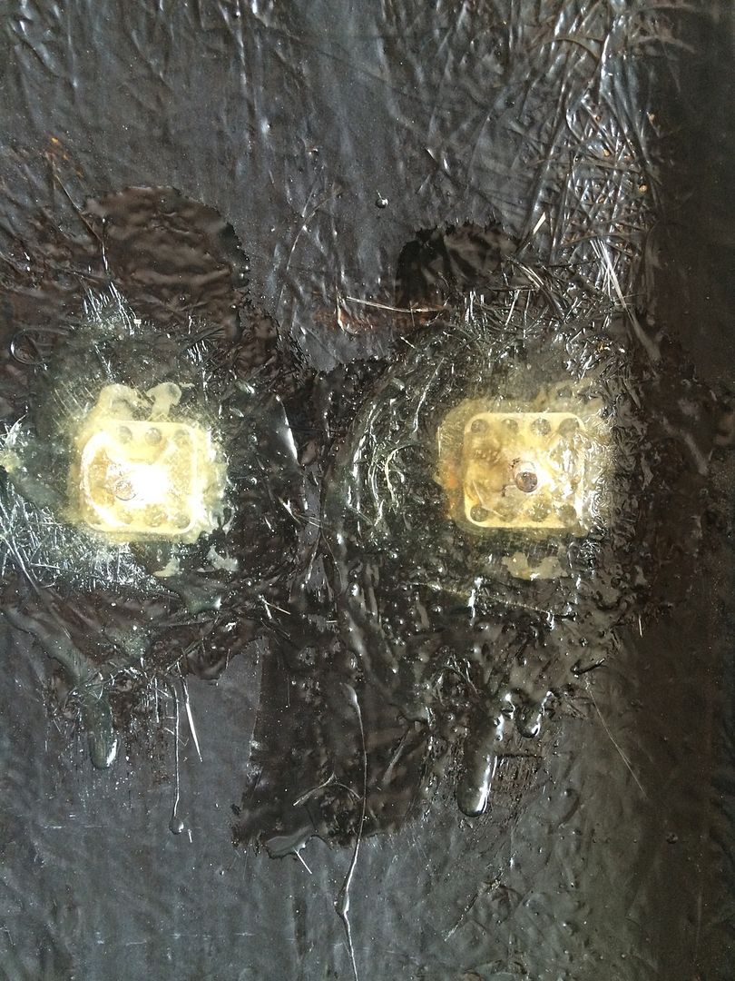 |
| Big heads after bonding |
 |
| not much thread poking through after shortening |
- I then added a couple of layers of fiberglass mat and resin, and ran a die down the threads to clean them before the resin was completely hardened.
- After an hour or so I was able to mount them on the brackets.
Refitting the wheels was a bit of a struggle, as the grp wings seem to be a bit narrower than the carbon effect ones and the sides come down a bit further, so it was quite a tight fit. I had to bend the brackets out slightly so they didn't rub.
Grill (or is it grille?)
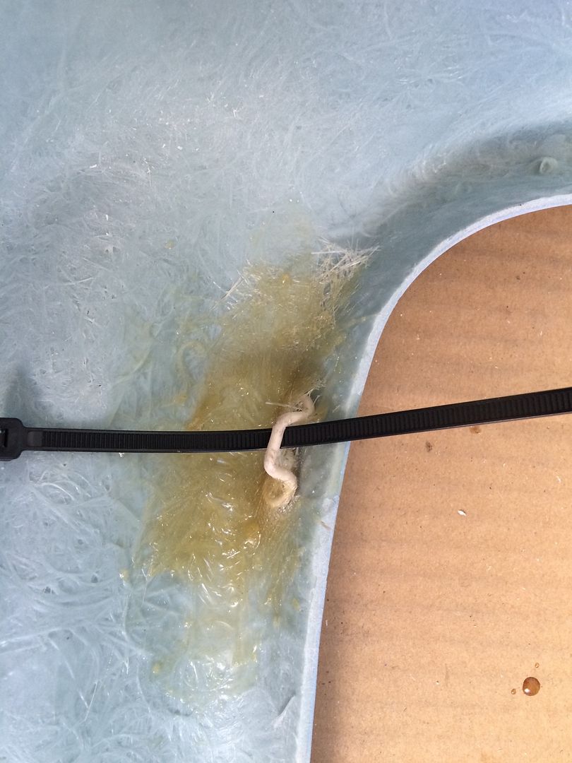 |
| tie downs made from bent electrical wire, bonded in place |
It really gives a very neat finish compared to the factory approach of drilling holes in the nose and threading tie-wraps through. The grill was secured with four tie-wraps from the inside.
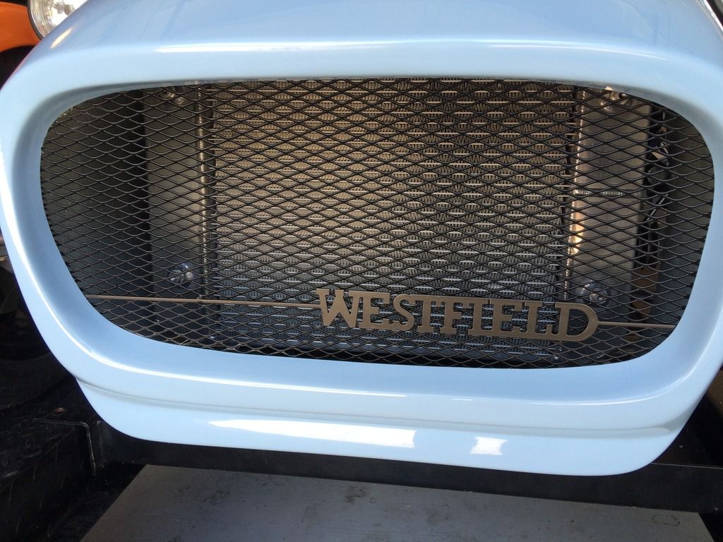 |
| The finished grill |
Monday, July 6, 2015
Time to do the jobs I have been putting off . . .
The last few days have been spent doing all the small jobs that I have been putting off.
Fitting the connectors for the rear lights
Fairly straightforward, so no pictures here. I just identified which wires were which on the loom and made up a plug on each side to fit. As I had put the reversing light on the right and the fog on the left, I was able to wire everything into a single plug on each side, after soldering all the earth wires together and adding a pigtail.
Boot box
Once that was done, I fitted rivserts to fit the boot box.
Only slight trouble for this was that one of the holes I drilled missed the body on the left hand side (there wasn't much to drill into for some reason on that side), so I had to do another hole, no big deal, as it won't be seen, but I know it is there. My rivsert tool died in the process. It was a cheap one I had picked up on eBay in the UK. Now I know why it was so cheap. I have not fitted the locks to the boot lid yet, as I am waiting for a replacement lid from Westfield.
Brake switch wiring
Extended the brake switch line so that it would actually reach the pressure switch (one of the problems of a LHD car).
Fitting the connectors for the rear lights
Fairly straightforward, so no pictures here. I just identified which wires were which on the loom and made up a plug on each side to fit. As I had put the reversing light on the right and the fog on the left, I was able to wire everything into a single plug on each side, after soldering all the earth wires together and adding a pigtail.
Boot box
Once that was done, I fitted rivserts to fit the boot box.
 |
| Time to play with the Clecos again! |
Only slight trouble for this was that one of the holes I drilled missed the body on the left hand side (there wasn't much to drill into for some reason on that side), so I had to do another hole, no big deal, as it won't be seen, but I know it is there. My rivsert tool died in the process. It was a cheap one I had picked up on eBay in the UK. Now I know why it was so cheap. I have not fitted the locks to the boot lid yet, as I am waiting for a replacement lid from Westfield.
Brake switch wiring
Extended the brake switch line so that it would actually reach the pressure switch (one of the problems of a LHD car).
Sunday, July 5, 2015
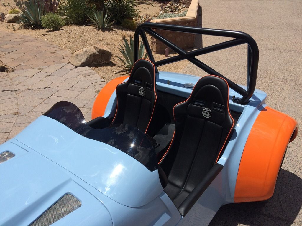
Half Cage
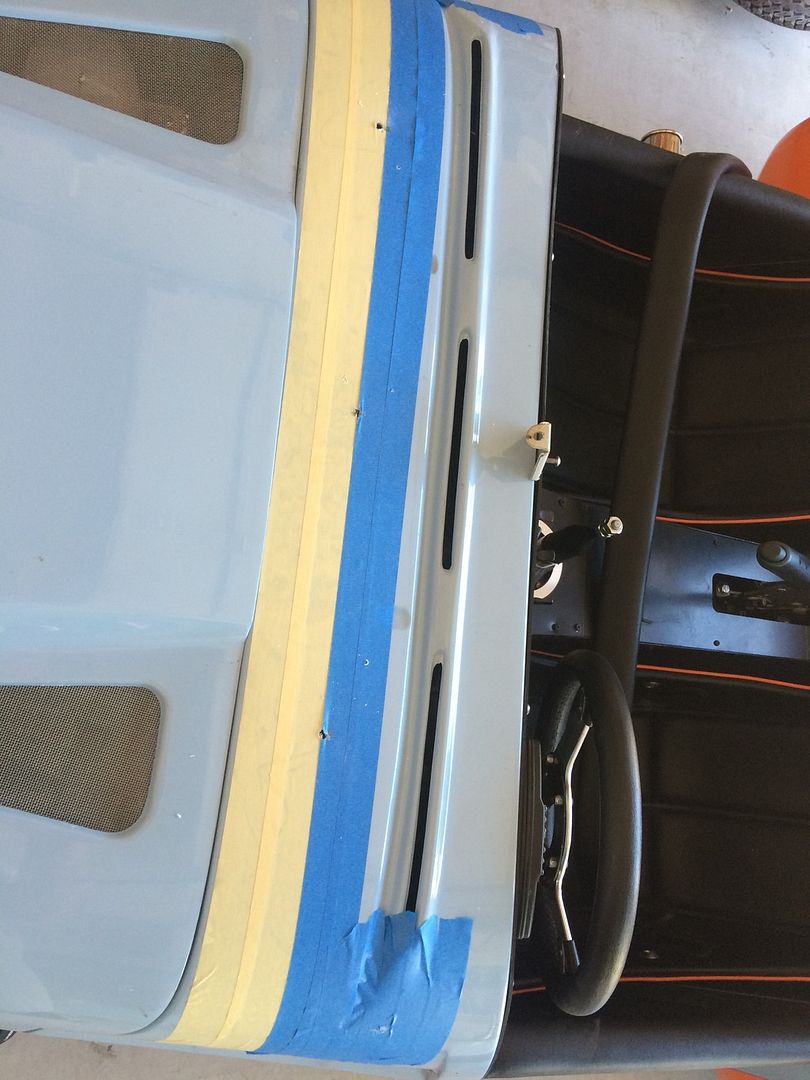
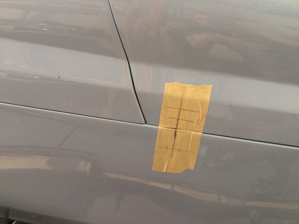
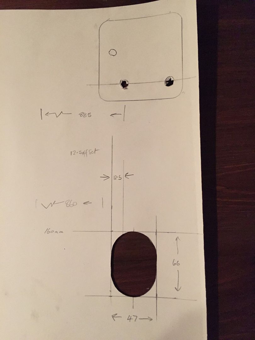
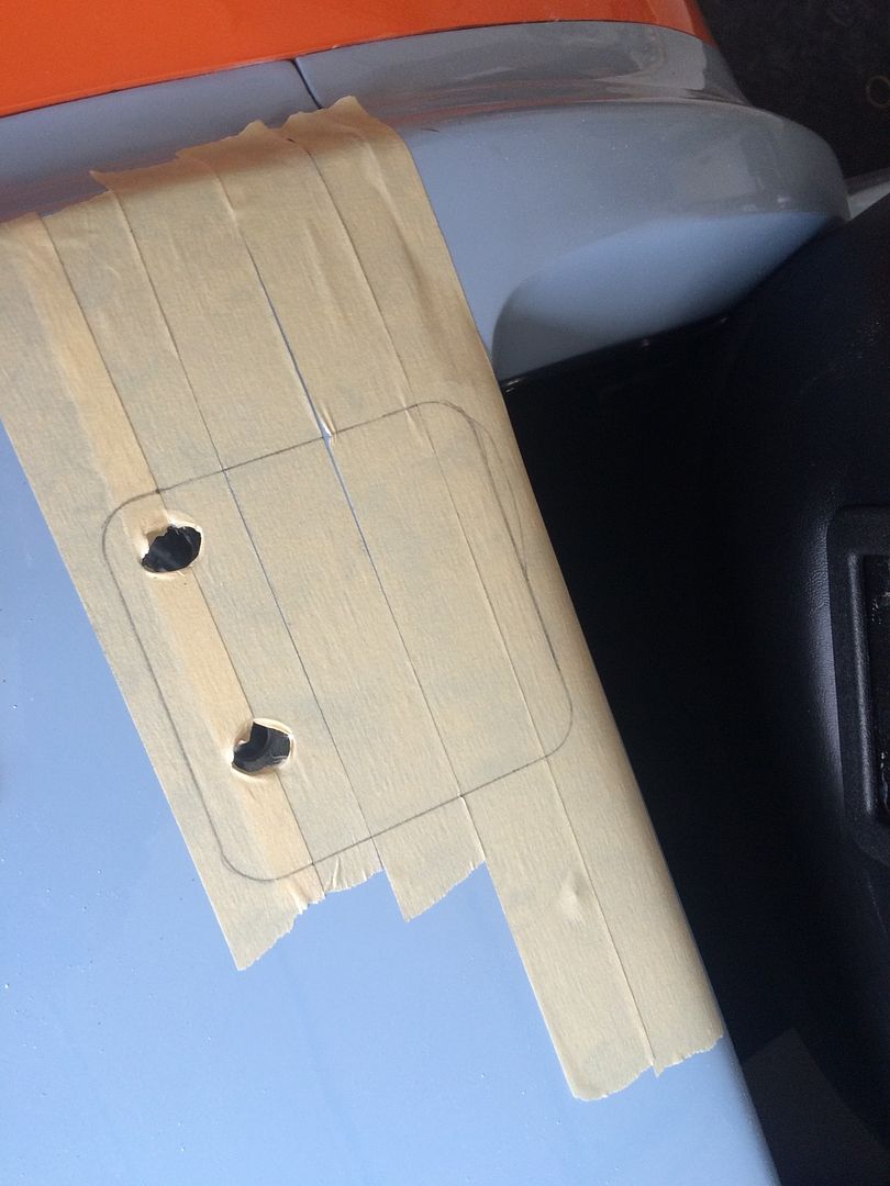
So, today was fitting the half cage, harness eyelets and gas cap etc. I haven't been looking forward to all this cutting, but with careful measurements it really wasn't that bad. I did use measurements for the holes for the rear stays provided by one of my fellow builders, which helped a lot. As the rear stays enter the body at an angle, you need to figure out an ellipse, but in practice an elongated circle works best. I also took a few other measurements, made a template in cardboard to check, and then transferred the measurements to the bodywork, after applying plenty of making tape.
Key measurements were:
I did think about using this as a template to trace the holes, but it was too difficult to line it up properly, just using the two bolt holes for reference. Transferring the measurements was straightforward.
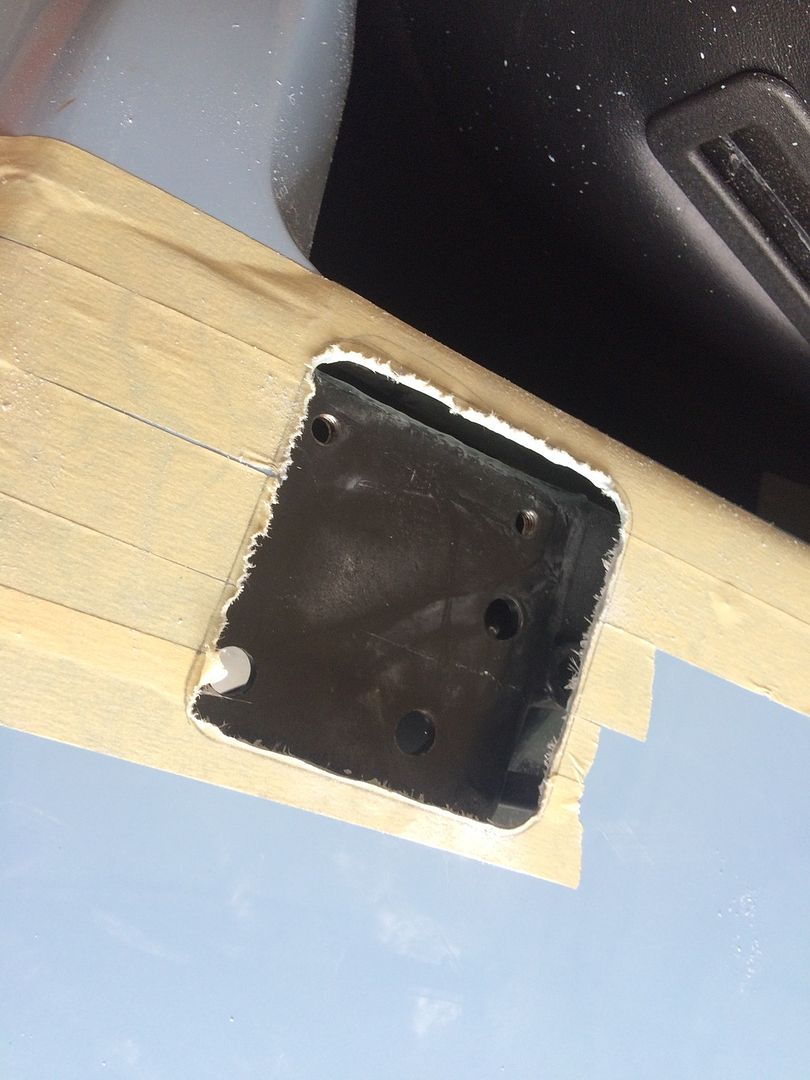
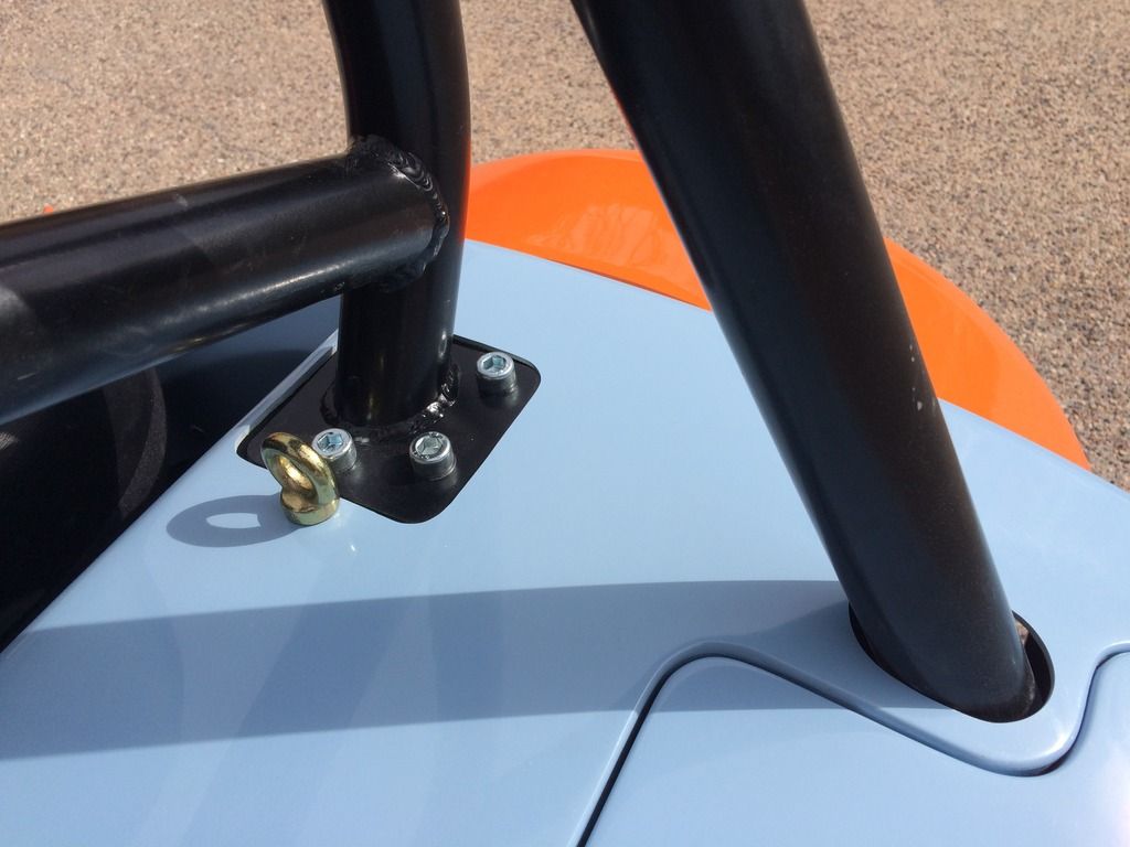
The side impact bars come with spacers to level out the cage in case you only fit the impact bar on one side. They were perfect to outline the hole for the front mount, after drilling up the holes from below. The spacer was not a perfect match for the mount, but it was close enough. Strangely enough, the third bolt hole wasn't drilled in the spacers, but the cone drill made easy work of that (I put the spacers in so that the height of the front mount was at the level it will be when the side impact bars are modified and mounted):
I then cut the hole undersize with a Dremel and then used a sanding drum on the Dremel to finish it off. Lots of blue/white dust everywhere! I took the masking tape off once I was close to the line to get nice straight edges (well, mostly straight).
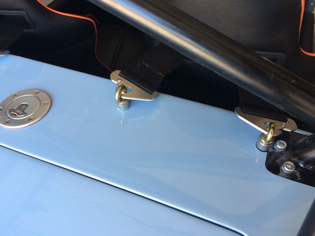
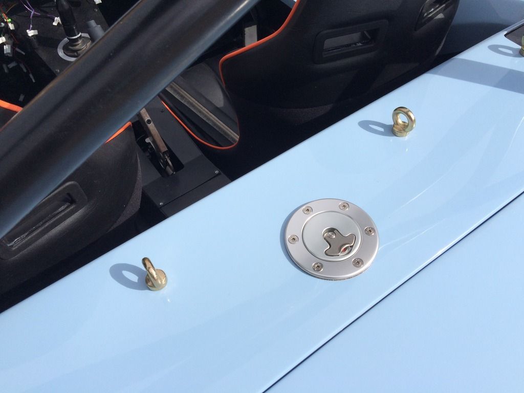
I used the masking tape template I had made earlier to locate the eyelet mounting holes - it worked perfectly - no measuring needed! You can actually locate the two end holes by eye, as they are right next to the hole cut out to mount the half cage. I drilled though the marked holes and checked via the boot opening that the drill was going inside the eyelet mounts. I then enlarged the holes with the Dremel:
The hole for the gas cap was located from the centerline of the two inner eyelets, using measurements I had taken prior to fitting the body. I used I a rattle can cap over the gas tank to stop any debris going in (and to mark the centre) and drilled a pilot hole to ensure I was centered. I then used a 2 1/8" hole saw, which was undersized and expanded the hole with a Dremel until the gas cap fitted. I then used the cap as a template to locate the mounting holes:
All in all it turned out quite well. I don't have the spacers for the eyelets yet, so they will have to come out, and the cage will have to come off to remove the outermost two!
Tomorrow I will screw in the dashboard and fit the aeroscreen - I intend to use the same method as for the harness bolts, making a template out of masking tape. If I have time, I will do the orange cycle wings also, which will info some fiberglass work.
I feel a trip to the DMV coming on this week, but first I will need to hook up the speedo sensor and check the oil pressure.
The half cage does sit high, but that is good. When you are upside down at the track, a bit of clearance is a good idea.
Key measurements were:
- Hole for rear stay: 47mm x 66 mm rounded to 47 mm diamater, which is the diameter of the spice jars in the kitchen, so I pinched a jar of curry for the job (see below)
- Spacing for rear stays (inside to inside): 860 mm. The rear stays are parallel on the half cage, so none of the tapering issues other builders have referred to with the FIA roll bars.
- Spacing for centers of innermost mounting holes on front mount: 885 mm. This means that inside of rear stay is offset 12.5mm from the centerline of the mounting hole.
- Centreline of mounting holes on front plate to inside of rear stay: 160 mm
The side impact bars come with spacers to level out the cage in case you only fit the impact bar on one side. They were perfect to outline the hole for the front mount, after drilling up the holes from below. The spacer was not a perfect match for the mount, but it was close enough. Strangely enough, the third bolt hole wasn't drilled in the spacers, but the cone drill made easy work of that (I put the spacers in so that the height of the front mount was at the level it will be when the side impact bars are modified and mounted):
 |
| No putting it off any longer. Time to get cutting |
 |
| Not too bad actually. Just need to go carefully with the Dremel as it has a mind of its own sometimes |
 |
| The moment of truth for the masking tape template experiment |
 |
| Gas cap hole drilled and ready to mount |
 |
| The finished item |
 |
| Hole around rear stay is a little oversized, but that is perfectly acceptable in my book |
The holes around the rear stays are a little larger than needed, but that is fine. I may get some rubber edging to finish them off. By the way, if you are careful, it is possible to do alone - you just have to attach the bottom stays to the chassis at the right angle first, so that the stays on the cage can just slide over them (do that before you fit the body). The lower bolt won't fit because the light housing is in the way - I am waiting for the right sized bolts so I can't do it up at the moment anyway. I imagine one bolt each side should be sufficient, given there is a single mounting bolt at the bottom (although it is a little thicker). I will have a think about this and possibly drill another hole so two bolts can be fitted - it will distribute the load in the event of inverted driving.
Tomorrow I will screw in the dashboard and fit the aeroscreen - I intend to use the same method as for the harness bolts, making a template out of masking tape. If I have time, I will do the orange cycle wings also, which will info some fiberglass work.
I feel a trip to the DMV coming on this week, but first I will need to hook up the speedo sensor and check the oil pressure.
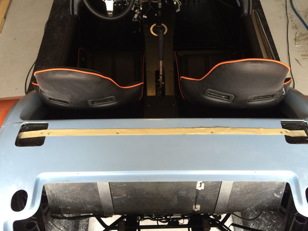
 |
| Half cage fitted |
The half cage does sit high, but that is good. When you are upside down at the track, a bit of clearance is a good idea.
Thursday, July 2, 2015
Nose-job
So after a day at the track yesterday (you know it's a good day when your tires look like this):
and you get to drive something that looks like this:
I spent the afternoon today fitting the body panels and nosecone. Hard to believe it would take the whole afternoon. I didn't have any bolts long enough to mount the nosecone support bracket (no surprise there), so finally I found some M8 bolts that didn't seem to have a use elsewhere and tapped an M8 thread in the mounting sleeves. I also managed to rummage through the various extra bolts and found another M8 bolt to attach the nosecone into the bracket, which had to be bent up slightly so the nosecone would meet it parallel. Cue the Birmingham Screwdriver!
Then fitting the bonnet and side panels and aligning everything was a lot of faffing, clamping and adjusting. I decided to rivet in the passenger side body panel first (as I had already started when I fitted the exhaust). I couldn't find any countersunk rivets in the kit (the manual said to use them, no doubt, I will find them when I am finished), so I just used the large-headed rivets provided, in the theory that they will keep the bonnet from rubbing on the side panels when fitted. Afer fitting that, I looked at the other side and the body panel was much further back, so I had to pull it forward quite a bit to get the same clearance to the front anti-roll bar and to square up the nose with the bonnet, which means the gap to the rear bulkhead isn't consistent from side to side. It won't be noticeable with the seats in place.
I cut a slotted hole in the bottom of the nosecone so that I could adjust the gap to the bonnet. Not that I intended to have a slotted hole, it's just that the first attempt was in the wrong place and it needed fettling, but a slotted hole is actually the best way to make sure everything aligns properly. It seemed that the nosecone was very flimsy at first, but once the three bolts are snugged up, it is quite rigid (but I am a little concerned that the rivsert is below the height of the body panel that the back of the nosecone sits on, so I may add a washer as a spacer, otherwise the nosecone may develop some cracks over time).
To make sure everything aligned properly before drilling the two top holes for the nosecone, I fitted the scuttle, which involved another trip to the hardware store to pick up some M6 bolts. Trouble was, I thought I wanted 16mm bolts, but I actually needed 20mm, so it will be back to the store tomorrow. For the time being, the 16mm held, but only just. To locate/align the holes in the scuttle, I used a trick of fitting a bolt in the rivsert first and putting paint on the top, and then placing the scuttle in the correct place. This marked the bottom of the scuttle and gave the exact spot to drill. I did the same for the nosecone:
Brilliant, if I do say so myself. I also ran around the locating blocks on the body panels with a Dremel prior to fitting to ensure a snug fit. Despite repeated vacuuming, there is now blue/white powder everywhere! The Triumph, which was sitting next to Mr. Westfield now needs a good clean!
Cutting the slotted hole in the bottom of the nosecone really helped getting the alignment with the bonnet correct. So perhaps it wasn't a mistake, after all!
Tomorrow, I will fit the latches and the locating pins/grommets. I am not entirely sure how to do it, but it will mean that the bonnet will be securely connected and won't fly off on any of my test drives. Hopefully the replacement bonnet will arrive soon, as this one sags due to the cracks that happened in transit.
Went for a short blat around the neighborhood. Have decided that 1st gear is nigh on useless, and the the turning circle is similar to a London bus!
I must say I am pleased with how Mr. Westfield is looking. His nose-job really helped. The half cage and fuel filler cap will be fitted tomorrow. The side impact bars need modification to work with the lowered floor. That will have to be done once it is all road legal.
I did get it insured yesterday, so with a bit of luck I can try to get it titled and registered next week, but there is still a lot to do. Orange cycle wings are on the list also!
 |
| I think this one is a little worn, sir |
 |
| Now let me see, where is the on button? |
Then fitting the bonnet and side panels and aligning everything was a lot of faffing, clamping and adjusting. I decided to rivet in the passenger side body panel first (as I had already started when I fitted the exhaust). I couldn't find any countersunk rivets in the kit (the manual said to use them, no doubt, I will find them when I am finished), so I just used the large-headed rivets provided, in the theory that they will keep the bonnet from rubbing on the side panels when fitted. Afer fitting that, I looked at the other side and the body panel was much further back, so I had to pull it forward quite a bit to get the same clearance to the front anti-roll bar and to square up the nose with the bonnet, which means the gap to the rear bulkhead isn't consistent from side to side. It won't be noticeable with the seats in place.
I cut a slotted hole in the bottom of the nosecone so that I could adjust the gap to the bonnet. Not that I intended to have a slotted hole, it's just that the first attempt was in the wrong place and it needed fettling, but a slotted hole is actually the best way to make sure everything aligns properly. It seemed that the nosecone was very flimsy at first, but once the three bolts are snugged up, it is quite rigid (but I am a little concerned that the rivsert is below the height of the body panel that the back of the nosecone sits on, so I may add a washer as a spacer, otherwise the nosecone may develop some cracks over time).
To make sure everything aligned properly before drilling the two top holes for the nosecone, I fitted the scuttle, which involved another trip to the hardware store to pick up some M6 bolts. Trouble was, I thought I wanted 16mm bolts, but I actually needed 20mm, so it will be back to the store tomorrow. For the time being, the 16mm held, but only just. To locate/align the holes in the scuttle, I used a trick of fitting a bolt in the rivsert first and putting paint on the top, and then placing the scuttle in the correct place. This marked the bottom of the scuttle and gave the exact spot to drill. I did the same for the nosecone:
 |
| just a little dab of rouge here . . . |
 |
| . . . and the spot marks, well, the spot |
Brilliant, if I do say so myself. I also ran around the locating blocks on the body panels with a Dremel prior to fitting to ensure a snug fit. Despite repeated vacuuming, there is now blue/white powder everywhere! The Triumph, which was sitting next to Mr. Westfield now needs a good clean!
Cutting the slotted hole in the bottom of the nosecone really helped getting the alignment with the bonnet correct. So perhaps it wasn't a mistake, after all!
Tomorrow, I will fit the latches and the locating pins/grommets. I am not entirely sure how to do it, but it will mean that the bonnet will be securely connected and won't fly off on any of my test drives. Hopefully the replacement bonnet will arrive soon, as this one sags due to the cracks that happened in transit.
Went for a short blat around the neighborhood. Have decided that 1st gear is nigh on useless, and the the turning circle is similar to a London bus!
I must say I am pleased with how Mr. Westfield is looking. His nose-job really helped. The half cage and fuel filler cap will be fitted tomorrow. The side impact bars need modification to work with the lowered floor. That will have to be done once it is all road legal.
I did get it insured yesterday, so with a bit of luck I can try to get it titled and registered next week, but there is still a lot to do. Orange cycle wings are on the list also!
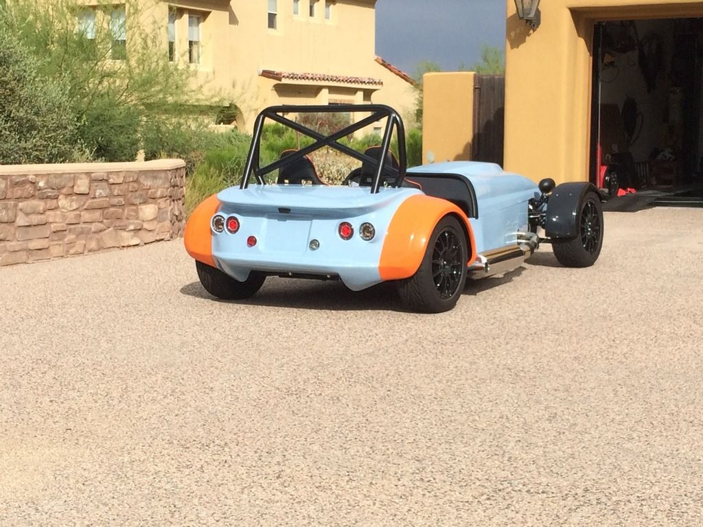
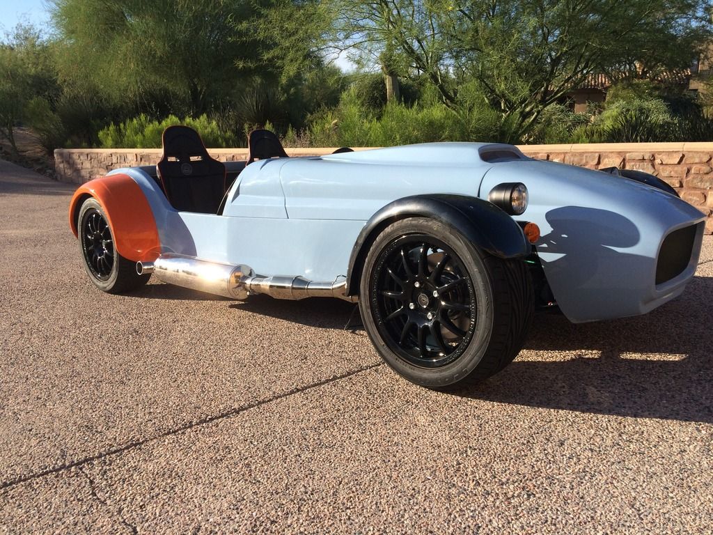 |
| Looking good in the driveway |
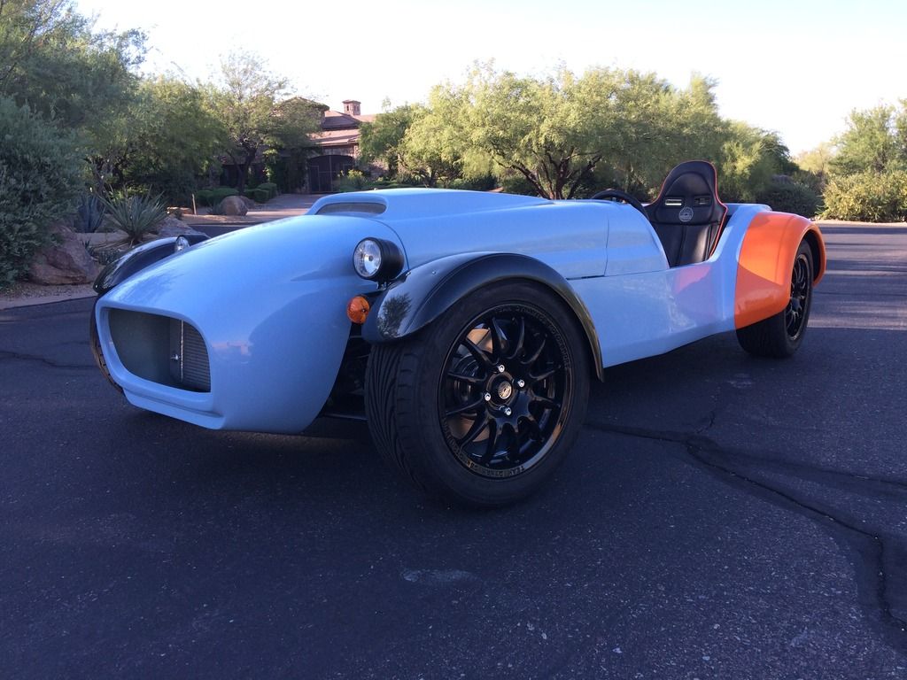 |
| A pre-blat photo-op |
The panel fit isn't perfect, but as this is intended to be primarily a track car I am not that concerned.
 |
| Mmm. I lost a seat somewhere |
Quite a difference from the Dutton that inspired it in 1984:
 |
| Mr. Dutton on Kingwood Common, all those years ago. Thinking about it, those wheels were way too small. |
Subscribe to:
Posts (Atom)