Sunday, May 31, 2015

Fiddling, Faffing and Fettling


Not much done today - a bunch of fiddling, faffing and fettling.

A52FC611-DC37-4A3F-AB49-AE60EA290712_zps
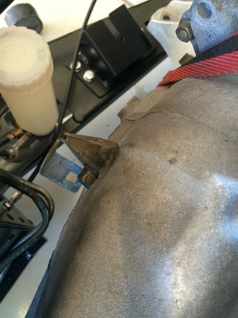
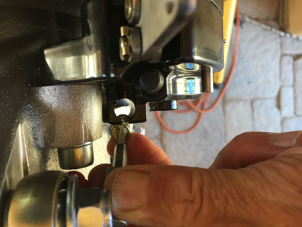
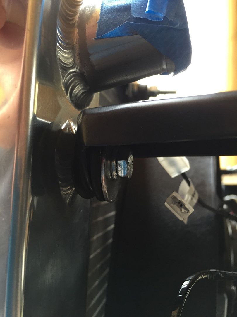
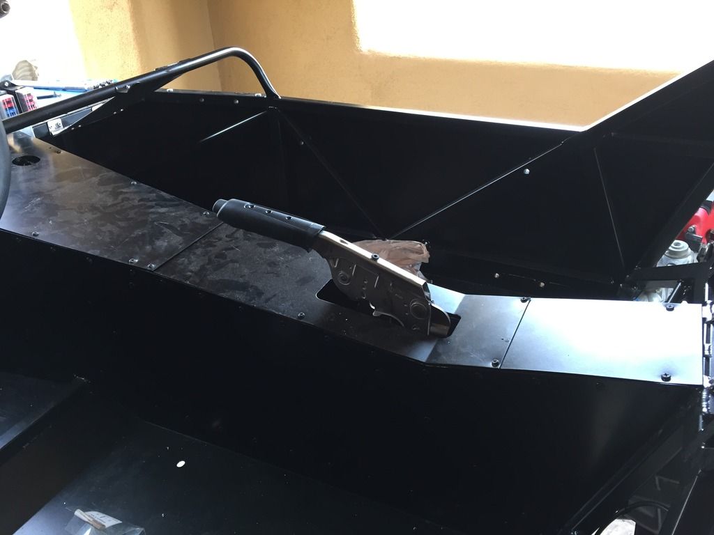
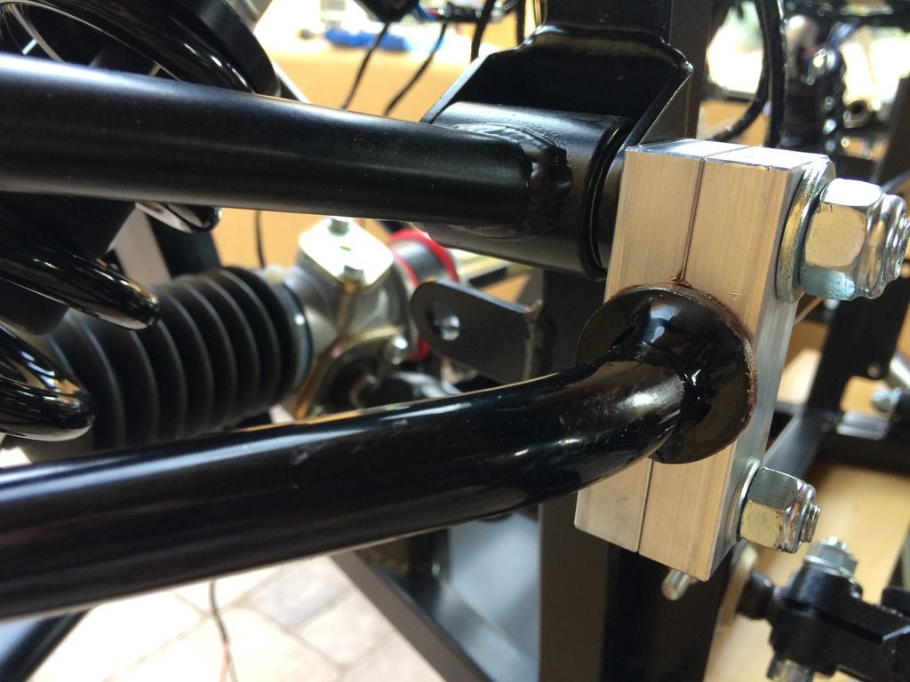
Gear shift sits high in the tunnel
Spent a bunch of time fiddling around with the gearshift gaiter - I just can't see how it is supposed to fit, and am wondering if it should really only be used if the car is carpeted.


9C792290-5BB2-45EE-917B-50E3E280B819_zps
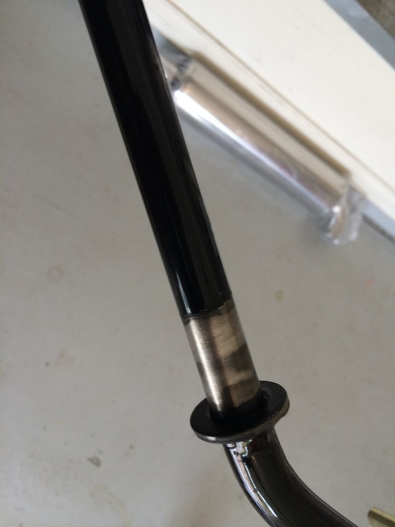
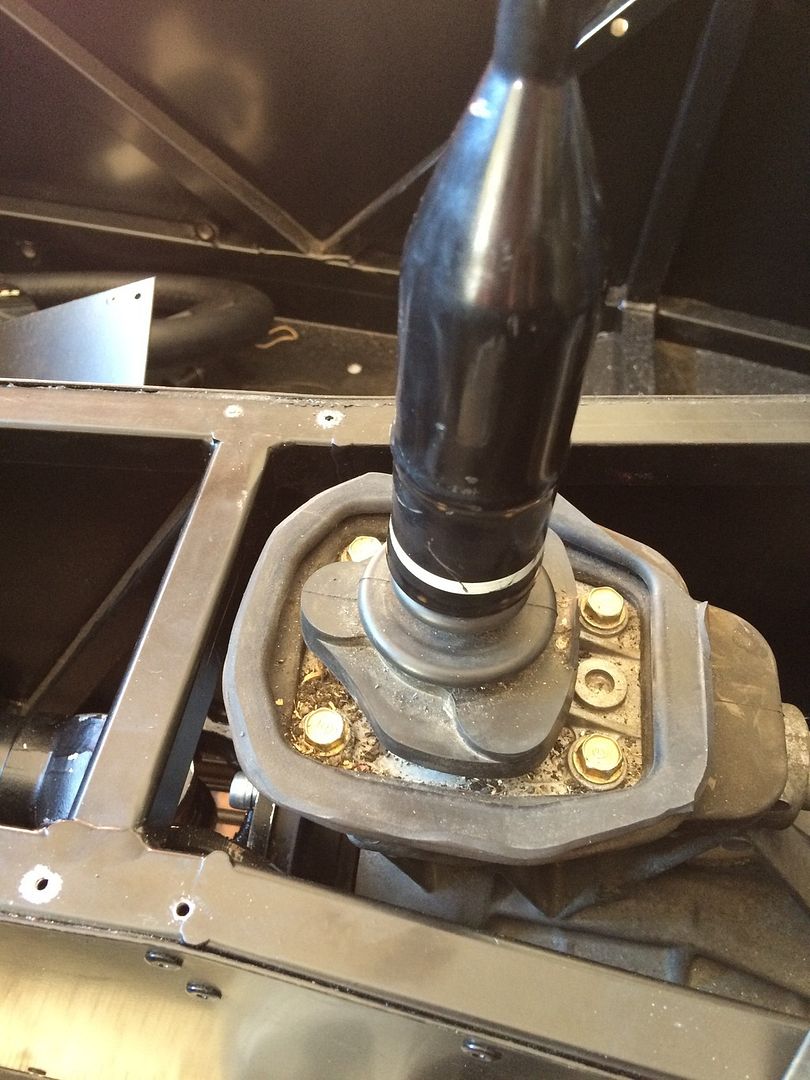
Gear shift with shiny ring, but no gaiter


I figure the ring with four holes in it is just to finish the hole (mine isn't very round!), as it doesn't seem to be a very good way to secure the gaiter (I see some builders have fitted the ring underneath to secure the gaiter), but there doesn't seem to be much (any) room between the rubber bottom of the gear shift and the tunnel top (I did cut down the rubber surround so that it would seal against the tunnel top, more or less).

I have not tried the handbrake gaiter, but that will be the same kind of issue.

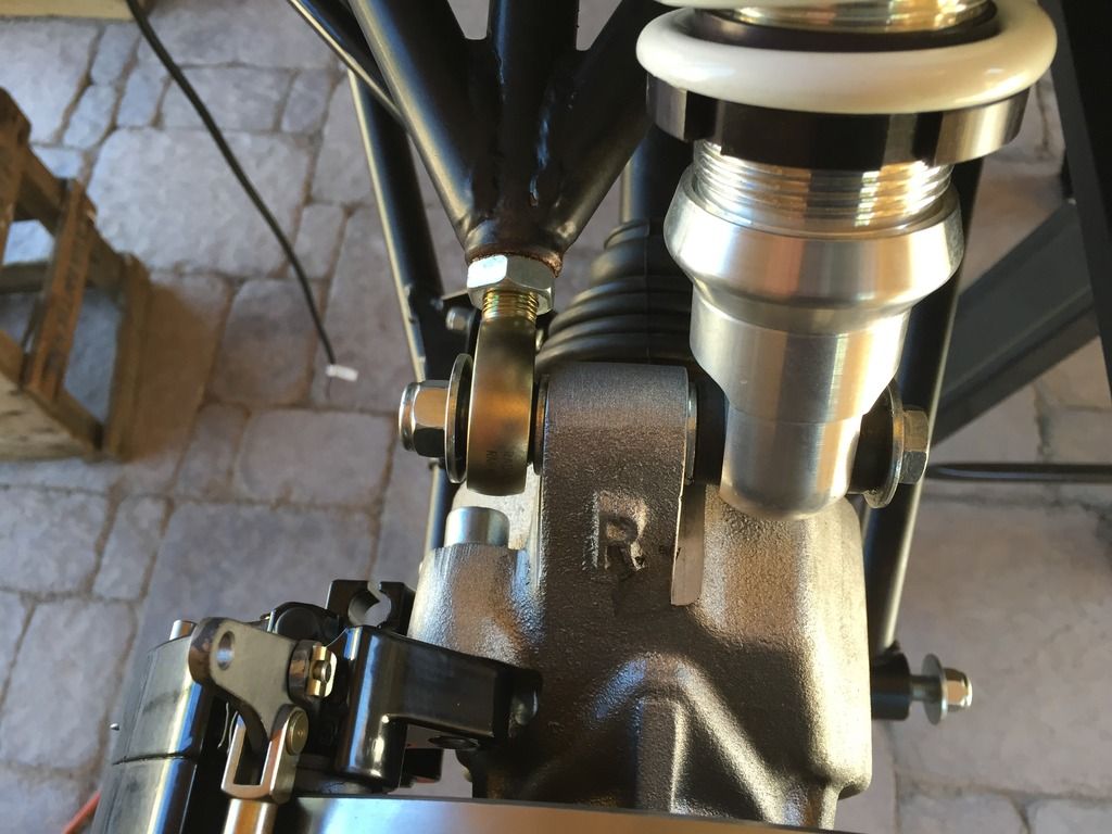
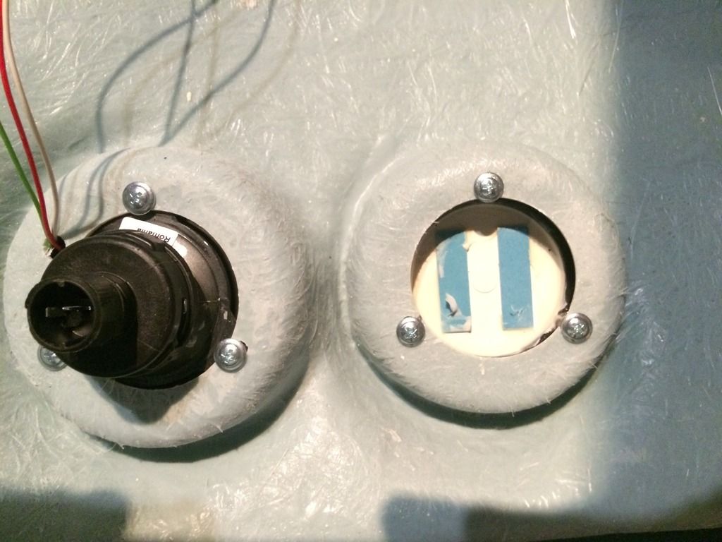
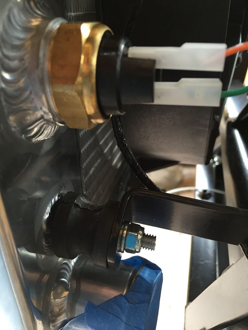
As others have noted, the reverse selector switch plug does not match with the plug on the harness:

E779B55C-EDAE-4F49-B106-BC0246D53842_zps
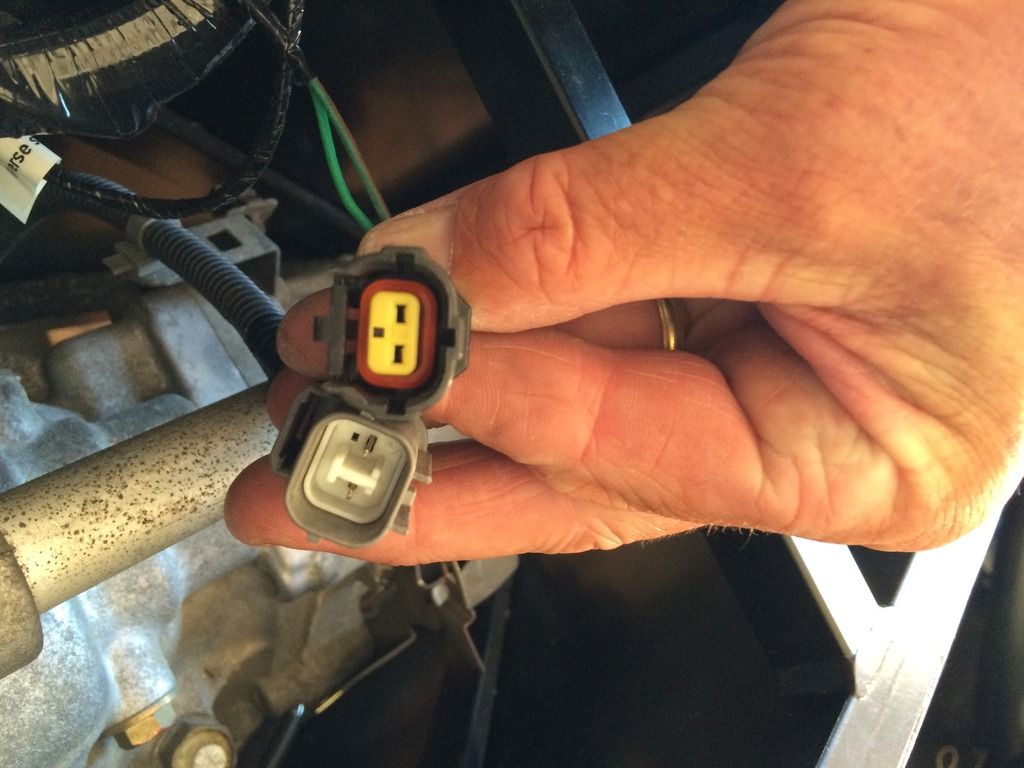
Honda plug, beneath, does not play well with Westfield plug on top

This is an easy fix - you can take the Honda plug apart to remove the two pins (I used a precision screwdriver to unlock the pins, which just pull out. These can then be fitted into one of the plug blanks provided with the kit. The Honda pins are slightly wider than those supplied, but it will go together.

4631115A-793C-41B3-AD31-F42648A65D6C_zps
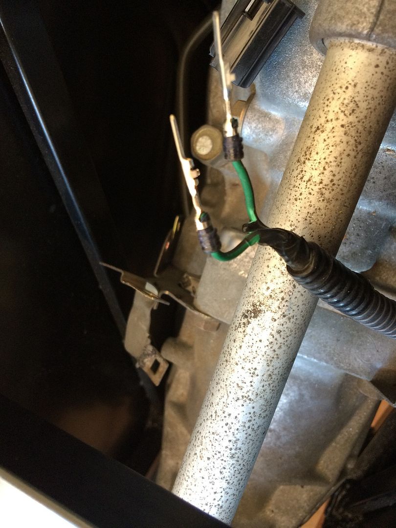
Pins removed from the Honda plug


AAB4922A-FB15-4B36-A851-1F90D2572877_zps
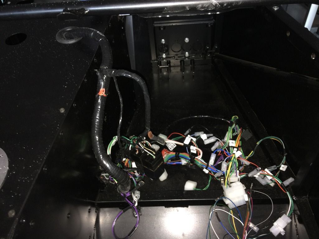
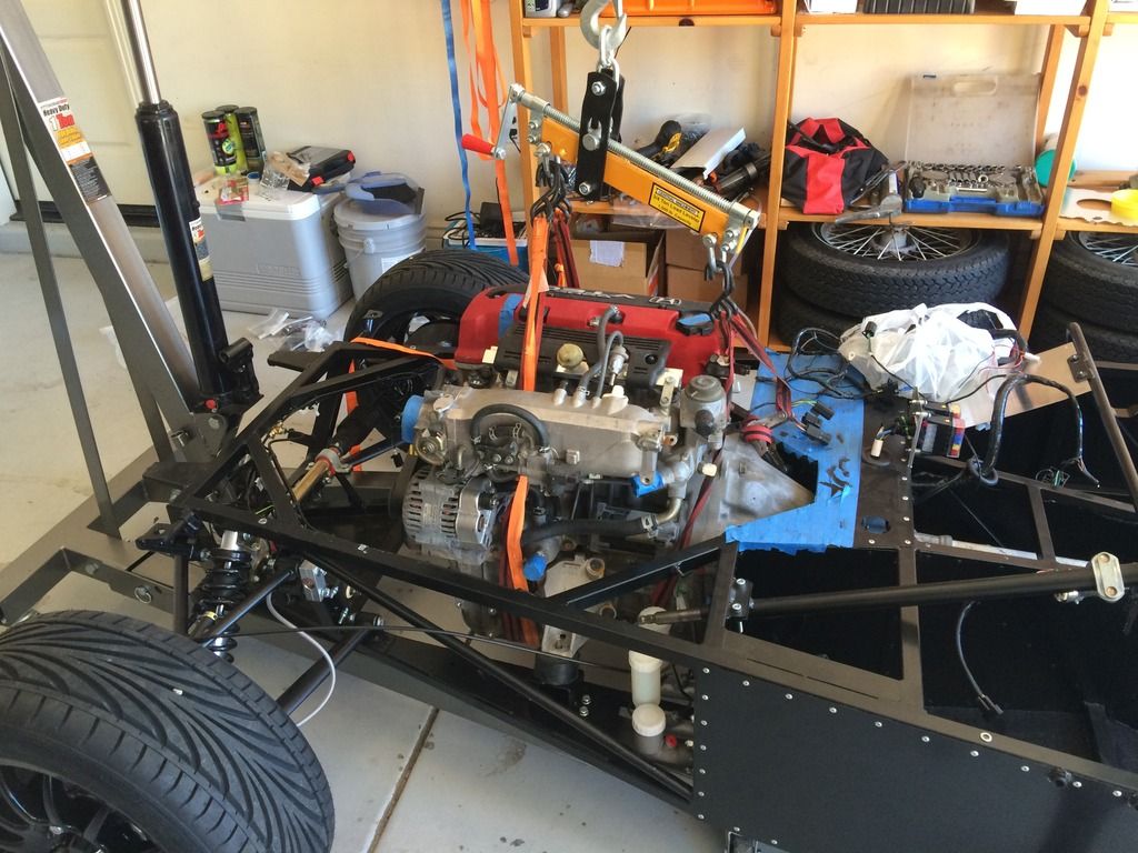
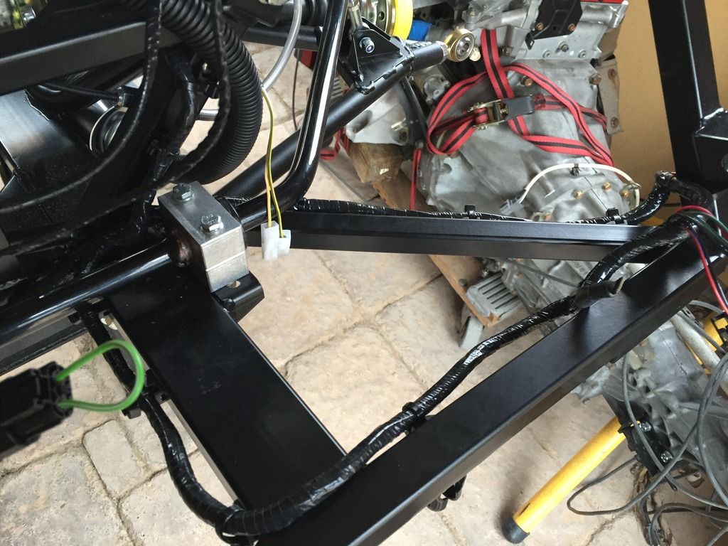
What a lot of wires - just need to figure out who goes where


All of the wires and connectors can be fitted though a single hole in the transmission tunnel top - no need to cut the panel as instructed in the manual - just take the relays out of their housings, separate the housings and feed them through before the rest of the harness (they won't fit through if you do the other wires first). Hopefully the engine harness will fit through as well - there is plenty of room.


Now all I have to do is to figure out which wires on the Dash 2 adapter harness go to which plugs. I guess I will need to look at the manual (normally my last resort)!

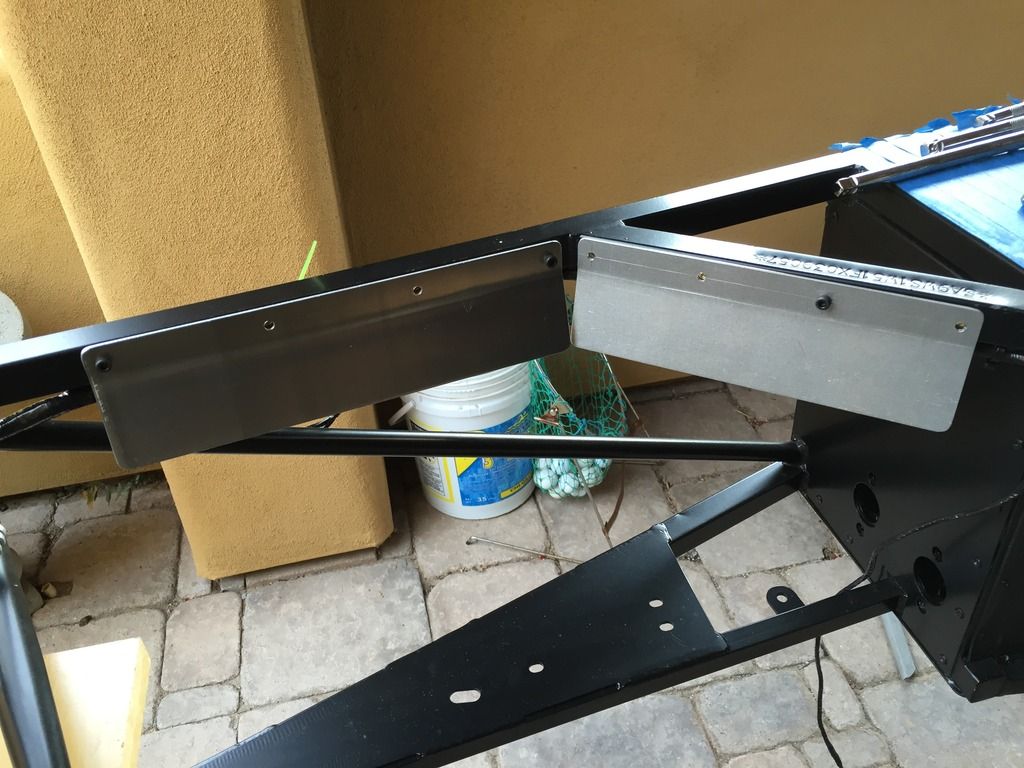
Another interesting thing - I took a look at the standard dash supplied and something didn't quite seem right:

2182D9CC-BA93-49E9-B558-759FEA62E705_zps
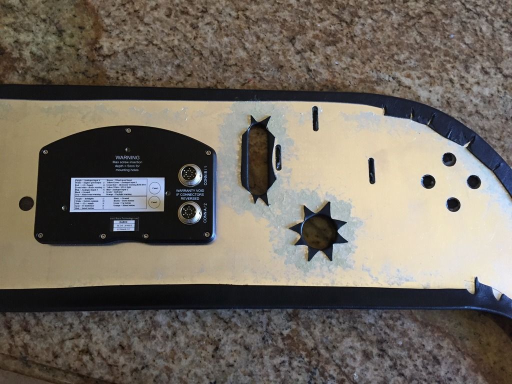
A mirror image of a RHD dash does not a LHD dash make!
In making the LHD dash, they had just made a mirror image of all the holes, so the mounting holes for the Dash 2 are on the wrong side:

Good job I checked before transferring the holes to the carbon effect dash they sent last week.
13411E84-CBF7-4705-93CF-676E7B5E7B33_zps
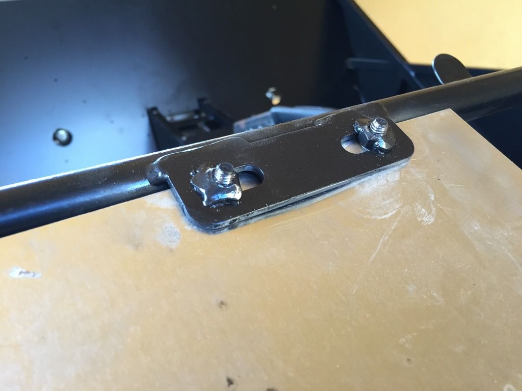
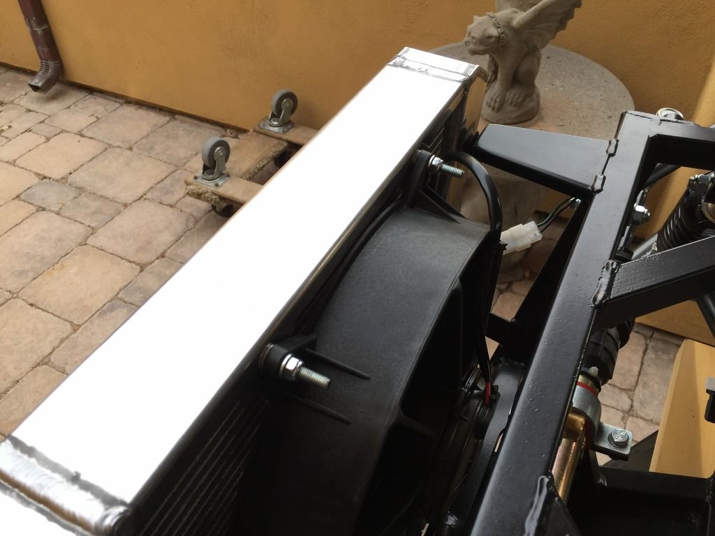
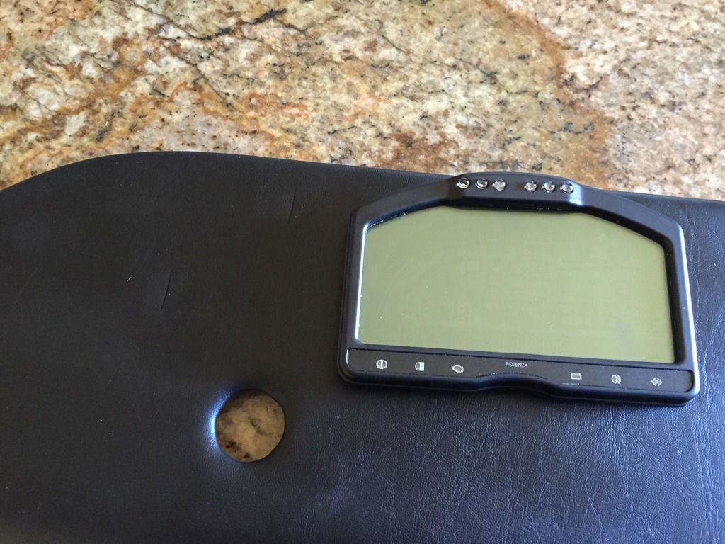
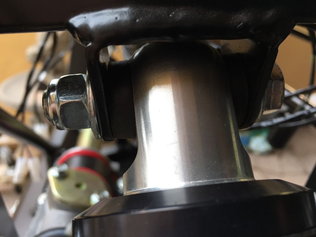
The unit is supposed to mount directly over the hole, which is for the steering column


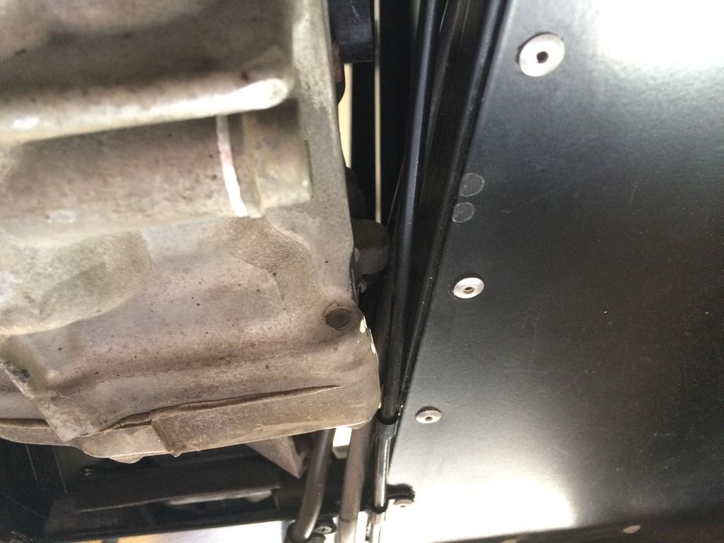
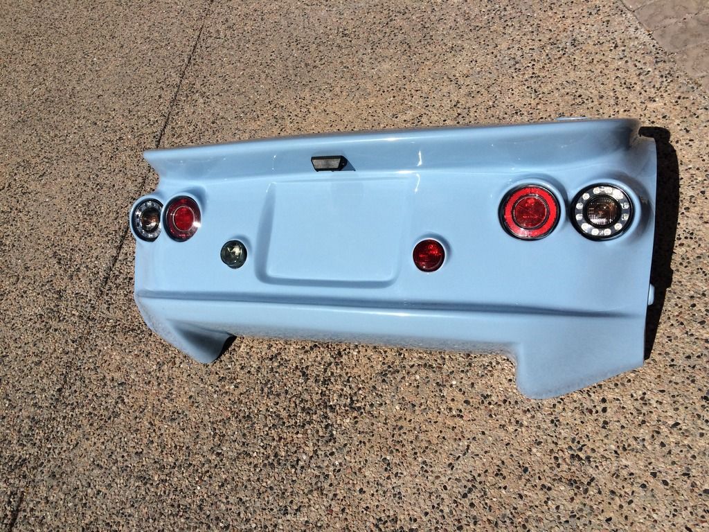
Also did some fettling of the rear body shell so that it would fit better - it is still a little tight with the body sides in so I will have to file it down a bit more. With adjusting the back shell, I am able to move the body sides back so they sit better, clear of the front ARB and so the rivsert in the chassis for the scuttle is actually covered by the scuttle, and not in the gap, as I have seen in some other cases. I will fettle some more later in the week - won't be able to get much done as I do have to work this week and have my retirement dinner in Chicago.

Apart from everything else it was 100 F in the garage today - a little warm to do anything really productive.


Friday, May 29, 2015

Fettling the Body

Bled the clutch today - it is possible from underneath, as I had hoped, but it isn't easy. The hardest part was fitting the flexible pipe. I didn't want to do it beforehand in case it got damaged in the engine install, but in retrospect it is best to do it first - it is so tight in there it is nearly impossible to get the bolt in - definitely use the Westfield-supplied bolt as it is shorter than the OEM Honda part, and therefore easier to get in. As other builders have mentioned, be careful about the bolts used for the banjo fittings - the longest one (along with thicker copper washers, if you have them) is for the master, and the shorter one is for the slave. They have different threads and you will strip them if you mix them up. You have been warned.

I also bled the brakes while I was at it, but will need more tomorrow, I did the old FART trick overnight to see if that helps. My Mini is parked underneath, so I hope there are no leaks!  I used my trusty Mityvac to bleed the brakes - so much easier than roping in an unwilling spouse.

Picked up some M5x20 bolts and nylock nuts for the handbrake cables - seems to be the easiest way of connecting them, as any cotter pins that would fit would be very thin.

Did some body fettling so I could get the rear on, but it needs more adjusting. I think it is feasible to fit the panels together on the car, rather than assembling them off the car then trying to fit them that way. It actually looks like a car. Doing the cutout in the scuttle for the steering column was a breeze with a grinding attachment on my cordless drill.

C6EC18AB-DE74-4EA3-B9EC-FD87E3A71C59_zps

C4D556BB-4322-46D5-8A9F-BE3A77694A7F_zps

By the way, on a LHD car there is no issue with clearance for the steering column with the alternator, so the fact that I had not put the spacer on the lower steering column mount seems to be a non-issue, thankfully. I did test the seating position while I was bleeding the brakes and the steering wheel feels too far away - that will be easy to rectify when I modify the column for the quick-release hub, which should add at least an inch by my estimation.


Thursday, May 28, 2015

Engine-in Day!

First of all, a very happy 65th birthday to my dear friend John. I hope you got what you were promised from Monique!

Went to the track yesterday and got gobbled up by an Indy car. This is what happens when a Lotus Elise meets a full-blown race car. I did point him by, but after that I was trying, honest!


Before we get to the engine, I did speak with Westfield about the side impact bars. It turns out they do not fit on the S2000 model and will need modification, due to the dropped floor. Also, the front mount has nothing to mount to. They are looking into it.

So, back to the engine.

You need to remove the steering column and the ARB to get the engine in, that is clear. I was hoping that I could leave the radiator in, but I quickly realized that I couldn't get the engine far enough back with the radiator in place, so off it came - no big deal, a two minute job.

I decided not to fit the mounts on the engine, but to locate them on the chassis - I figured this would give additional clearance to get the engine in - it is quite a lump. In retrospect, I think the best approach is to leave everything off and fit both the rubber bobbins and the mounts once the engine is more or less in place - that is what I ended up doing.

A load leveller is essential. Even with that, I had to jack up the rear of the car.  I had a few problems - first one of the engine loom connections snagged - hopefully I didn't do any damage. I had left the rear support for the fuel rail in place - that was catching, so it had to come out. Then there was a bracket mounted on the gearbox that I had not removed - on the left hand side, it stopped rearward progress. None of the other builders had mentioned it so I had not thought about it - fortunately, I could take it off without having to pull the engine out. The offending bracket is shown to the left - I am not sure what it is for, but it is not needed on the Westfield, so off it came.

I was hoping I could get the engine in with the exhaust manifold on - you can, but you need to tilt the engine significantly to the left to do it - it is not for the faint at heart - it is an extremely tight fit, as the alternator on the other side snags on the chassis rail and brake line. I did manage to do it though, after removing the heat shields. If I had to do it again, I would remove the manifold (or not fit it in the first place).
Don't let anybody tell you otherwise, it is an extremely tight fit.


I think I will have to reroute the fuel pipes - I had taken them through the tunnel and then under the gearbox mount:


They just touch the gearbox at the point where the nub has been taken off. A better approach is to take them further back in the tunnel and then down after the gearbox mount, where there is more room. I think I will cut them and put in flexible hoses, it seems a lot easier. It is just too crowded at the point I ran the lines out:


Also, if you fit the ABS panel with the footrest on the right hand tunnel, it snags on the gearbox - Westfield have only just provided me with the correct aluminum plate - if you are building a LHD car make sure you have two aluminum footwell plates and do not use the moulded ABS one with the footrest. I will leave it as is for the moment, but it is less than satisfactory.

Apart from those minor problems, it all went fairly smoothly. The gearbox mounts were a non-issue - I secured the engine mounts and then reached down in the transmission tunnel and drilled the gearbox mount holes through the gearbox mount. I then jacked up the gearbox and was able to slip the rubber mounts in easily enough. It did need a fairly slim drill though - my cordless drill wouldn't work, so I used a pneumatic drill instead which worked a treat.

I didn't bleed the clutch on the way in, as other builders have suggested. As I have the luxury of a four-post lift, I figure I should be able to get at the bleed nipple from below - we will see tomorrow. All in all, it is a pretty formidable looking beast. However, I doubt it will keep up with the Indy car!
I even test fitted a couple of panels. Because the rear bulkhead isn't in yet, I can't fit the panels permanently, but I think I will mock everything up tomorrow, using my trusty Clecos.
Here is an updated time-lapse, including getting the car out of the courtyard and inserting the engine. A new video starts tomorrow.


The last two days have been very taxing woking alone. Ron T. I could have done with your help. Shame you are not here!

With a bit of luck, tomorrow it will look like a real car.


Tuesday, May 26, 2015

We Have a Car!

The uprights arrived finally yesterday, so today was a busy day of fitting the four corners, attaching the brakes and putting the wheels on (yay!). Found that the handbrake cable was too fat for the hole on the calipers, so I used a hand file to make the hole slightly larger:

 44AE8F7A-964A-4E94-825F-7CB93CEB1295_zps

Everything went together really easily, however, the bolts for the upper mount for the rear uprights were too short - I have a feeling it is because the Protech dampers are a little wider. I don't have any thread showing through the nylock nut at all:


9E05B0C2-E64D-40E4-96E8-9AD6E7A0A1A3_zps

Torquing up the balljoint nuts on the front suspension was possible using a wobble bar attached to the torque wrench - it gave just enough flexibility to be able to access the nut.

So I got the car down off the build stands using my engine hoist and trolley jack - that was the easy part of the afternoon - I now have a car in my courtyard:

1E09343F-B5B7-420D-9A3B-058DA13871DC_zps


3319AE8E-E8DD-4D1E-9312-10F1A29DEA83_zps

I knew it wouldn't get through the gate with the wheels on, but I thought it would just fit through with them off - unfortunately I was wrong - it was about 1" too wide at the rear. I had expected this, to be honest, and thought that if I was able to tip the chassis on its side I would be able to get it out - easier said than done! I finally did it using the hoist and the jack again (hoist at the rear right corner and the jack under the front right wheel). It was a bit precarious, but I was able to get enough of an angle to get the rear hubs out and back on its wheels:

D3EFDDFF-B2DE-4870-B0ED-DC072B770D43_zps

The front is slightly narrower, and I just put it on a dolly after taking the wheels off and took it out at an angle - all in all the operation took about 2 hours - would have been a lot easier/quicker if I had had an assistant!

I now realize how tiny this car is - here it is next to my TR3, which is not a big car at all!

F221A97E-EDF6-496E-A69E-ECC191036F2A_zps

The Westfield will now be living in the garage, so I can put the engine in and get everything connected up. This will be on Thursday, as I am off to the track tomorrow. The four post lift should make working on it fairly comfortable.

F48EEE60-DE2C-4CAB-8CF5-A60A2F65E6C6_zps


I also received the side impact bars yesterday, but I can't for the life of me see how they will mount - it looks like they should mount under the roll bar and then under the floor using the seat mounting holes, but nothing lines up - also there is nothing to mount the front to - it doesn't line up with any of the threaded inserts in the chassis - another question for Westfield.

Monday, May 25, 2015

Waiting for Uprights

The uprights are on their way! Westfield were true to their word and shipped them out, along with a number of other parts, at the end of the day on Friday. Have been tracking the parts from Westfield - they should arrive on Tuesday at which point, if all goes well, I will be able to get the wheels on the Mr. Westfield and get him off the build stands, ready for his engine. In the meantime . . .

Captive nuts welded in
In the search for things to do while waiting for the uprights, I welded in two captive nuts to support the ECU panel. Now all I need is the ECU. Hopefully that should be shipped out this week.


I also wanted to see how the body panels fitted together - there is now a car in my guest house.  I realize now that the rear bodywork needs trimming to fit over the chassis - fitting the panels together made that clear. The panels all went together well - they had all been pre-drilled, which was a surprise - I was not expecting that. However the rear wing does not fit well near the lights - it doesn't look like it can be adjusted. There may need to be some disguising done here, as I doubt the gelcoat is thick enough to stand sanding/rubbing down.

Do you know there is car in your guesthouse?


It is exciting to see the Mr. Westfield looking like this - can't wait to have the body on the chassis. Unfortunately, while testifying the rear panel, I noticed a crack in the finish - caused in transit - looks like I will need a new one.

Small star crack on rear bodyshell


Thursday, May 21, 2015

Rear Bulkhead

I have been mulling over how to efficiently fit the rear bulkhead, given a lot of people have said it is a pig of a job and it invariably buckles and a lot of masking tape is needed to prevent scratching the other panels. As mine has a dent in it and will probably be replaced, I decided to have an experiment. Because the top of the panel is folded over slightly, you will always get a buckle to some extent - also, because of the cutout for the transmission tunnel, the middle is the weakest part, again contributing to the buckle. The trick is to minimize this. one of the other builders online suggested bending the panel around something curved (I think he mentioned his butt - water butt that is), which got me thinking.

So here is the solution. I tied a knot in the end of a piece of electrical wire and threaded it through one of the rivet holes in the bulkhead from the front. I used one of the holes halfway down the side, I then stretched the wire across the back of the bulkhead and threaded it through the corresponding hole on the other side. I then pulled it tight, so as to bend the bulkhead like a bow, until the length of the wire measured just under 40" (that is the width of the inside of the chassis frame), then bent the wire over to hold the bow in the panel. It was then straightforward to put it into place, with no scratching of the other panels at all (no masking tape needed), and finally release the wire. Removal is the reverse of fitting (where have I heard that before?).

So, here is the process in pictures:

1) first, thread a wire through one of the rivet holes from the front (here is the knot I put in it):


2) pull tight, like a bow (I used wire so it would be easy to hold the tension just by bending the wire back at the other end):

3) ensure that you are just under 40":

4) insert bulkhead, with no damage to the other panels, and minimal buckling. Then remove wire, once the panel is completely in place:

Only the slightest amount of buckling in the middle, which will go away, once riveted. It took less than 5 minutes to do.

You can see the dent in the lower right hand side as we look at it. I know it will be behind the seat, but it won't be covered with carpet and I will know it is there - which is why I am waiting for a replacement from Westfield.

Idle Hands . . .

Still waiting on the uprights - let's see if they come through and they arrive at the factory tomorrow.

Gearbox mount before and after surgery
In the meantime, the gearbox mount needed cutting down, so I did that. Fairly straightforward - just need to cut off all the spurious bits on the sides, as it is mounted from below via the holes you can see. Quite a neat job - shame we won't see it!

Still figuring out how to locate the holes for the mount - nothing is predrilled - looks like I will have to put the engine and gearbox in, mark where the holes go, remove the engine and gearbox (perhaps just a little bit), drill the holes, then refit the engine and gearbox. Sounds like a bit of a faff. Am wondering about making some slots in the frame in the approximate position the mount so I can just drop it straight in.


Manifold before and after attack with a Dremel

I also took a look at the exhaust manifold. Looks like it was welded by a monkey, or a two year-old, or both. Decided to clean up the inside for better gas flow. That must add More Power!!!!


As I have done the gearbox mount and cleaned the manifold, I decided to get the engine ready for installation - removed the old manifold and heat shields and fitted the new one - the nuts (which should be replaced each time you fit the manifold) should be torqued to 23 lb.ft - 31 N.m.

Switched the oxygen sensor over also.


Apparently, there is a little nub on the gearbox that needs removing, otherwise it won't fit, so "off with his head"!


Also removed the MAF sensor, and fixed the blanking plate, which needed trimming. The screws were also too long, so I cut them down after threading them into an M4 die to recapture the thread afterwards. The rest of the engine blanking etc will be done once it is installed.  I had a trial play with the engine hoist and load leveler to ensure I could suspend the engine from the block to leave enough room to get it in. As everybody who has built one of these has no doubt experienced, it will be tight!

Had a lot of snake problems today. Again, one was coming into the garage as I was walking out - was able to shoo it out - it looked remarkably familiar. It went into the same hiding place as before. After a while I thought it made a run for it and I found it hiding under a bushy cactus - however I went back to its hiding place under the house and it was still there! This means there are at least two of them (three counting the one that was taken away the other day). Here is the security guard getting rid of him. He had a fight with the other one and it got away and hid under the house again. 


Tuesday, May 19, 2015

Time lapse

Here is the first installment of the time-lapse video, documenting work to date. Boy do I work fast!


Brake Lines

I cut the front brake line and reflared it (not forgetting to add the new fitting first!), now the lines fit nicely. Also made up a new line from the master to the brake pressure switch.  Top tip when using a flaring tool - add some oil to the die, it makes the formation of the flare a lot easier.
50 year old brake master line

I remembered I had some of brake tubing left from when I restored my Austin-Healey - they don't make brakelines like those any more - 50 years old, no corrosion in or out and really solid. I used a piece 11 inches long for the pipe - just a little longer would be more comfortable. I also painted it black to match. Now somebody please tell me why Westfield supply a pipe that is less than 6 inches long for this?

As I am now at a standstill, I have turned the time-lapse camera off. Watch this space for the first installment of the video!

Monday, May 18, 2015

Rear Body

I am pretty much at a standstill as I am waiting for parts from the factory. They now tell me that they expect the uprights in on Friday. Not the first time I have heard that so I am not holding my breath.

Couldn't reflare the brake lines as I couldn't get the correct tool locally - was able to get one quickly online (same-day delivery from Amazon), so will finish the brake lines tomorrow - will pick up some brake tubing so I can make a master to brake pressure switch line of a sensible length.

The snake was back again yesterday - I nearly trod on it as it was coming into the garage as I was walking out - I was on the phone and was not paying attention. Now I know why they tell you not to leave the garage doors open. Security came to take it away - it wasn't too happy about being picked up.

As there isn't much else I can do, I fitted the rear lights:

Pretty lights
It took a lot longer than I anticipated. After bonding together the reflectors on Sunday, I decided to fit them first - I had the bright idea of using one of the indicator assemblies to mark the holes for the self-tapping screws by centering it in the large hole - however the hole isn't central in the moulding, so the reflector wasn't centred - slight fettling of the holes sorted this out. for the other assemblies, I took a slightly different approach - I drilled the bottom hole first, slightly oversize, and then used the indicator light assembly to position the two other holes - that worked a lot better.

As the LED ring/indicator assembly has mounting holes, I decided against bonding (the approach suggested in the build manual) and just screwed them in in the same way as the reflectors, being careful not to use screws that were too long - I checked the LEDs worked before and after screwing. I had found 12 screws in the body attachment kit, but they looked too long, so I replaced them with 1/2" self-tappinig screws that held fine and have large heads.

Lights form behind the curtain
Here is what it looks like from behind (viewed upside down). The use of large-headed screws means the holes could be drilled oversize for easy centering. Some of the holes were right on the edge.

I couldn't find enough M5 nyloc nuts in the body fitting kit to fit the reversing and fog lights, so I took them from the cycle wing fitting kit (they had sent me two as I had ordered both the grip and carbon effect wings). I put washers under the tabs of the light assemblies and I noticed they do not sit flush and were bending when the nuts were tightened up.

Fitting the numberplate light was straightforward, with the exception of drilling the hole for the locating pin on the wrong side! That was an easy fix.

I would try fitting the body, but I don't have the rear bulkhead in place (waiting from the factory) and I am not sure the car will get out the gate without being tipped on its side, so I will think I will wait.

Found a crack in the gelcoat on the rear panel while I was working on it - another victim of the poor packing.

Sunday, May 17, 2015

Eeek!

No progress today but did have a run-in today with this fellow swimming across our pool. Turns out he is one of the good guys - he eats rattlers, mice, rats etc.  Still, bit of a nasty surprise, it was at least 5ft long.


My new best friend

Saturday, May 16, 2015

Front Brake Lines


Well, did a nice, neat installation the front brake lines (I waited until the suspension was in to make sure there was no fouling on the front ARB as suggested by the manual, but it turns out this is not an issue with the sport turbo version of the ARB. However, after getting the pipe from the master cylinder to the front tee formed, I just couldn't get the threads to engage - spent 20 minutes trying, being careful not to cross the threads. 


Brake line routing around the front frame
Then I remembered seeing 2 spare unions in a bag amongst all the other bits and pieces, so I tried one of them and it fits perfectly - turns out the brake unions fitted on the brake pipes do not fit the master cylinders used in the bias system (thanks for telling me Westfield - why didn't you tell me when I told you the master to brake pressure switch was too short?), so now I have to try to reflare the pipe without losing too much length.


Incidentally, if you bring the line straight up and then along the front chassis rail (not along the round diagonal) it is just the right length. A lot of other builders have found it to be too long - I think that's because the manual says to follow the diagonal, which as we all know, is a shorter distance.

At least I get to buy a new tool. Hopefully I can find a flare tool tomorrow.
Indicator pods

Have ordered these from a company who makes parts for Westfields in the UK - No, they are not toy binoculars. I don't want to mount the front indicators on the side of the nosecone - these little pods will allow me to mount them under the headlights, the same as on a Caterham.

Friday, May 15, 2015

No Progress Today

What with the rain and all

When it rains here, it rains:

When it rains, it pours
I did get one of the front brake lines in.

Crawford came by and picked up a brake line mounting clip and handed it to me. He has officially participated in the build. Well done Crawford!

Mr. Angry spent the best part of an hour on the phone with Westfield his morning arguing about the sizes of bolts included in the kit (some are not long enough for the intended purpose), and about the missing uprights - apparently it is not their fault, as the supplier won't call them back. Not a good sign. I have promised to pester them every day until I get my bloody uprights - this is holding me back - until I can get the wheels on I can't put the engine in. Mind you, even if I did get the engine in, I wouldn't be able to get it to work, because I don't have the ECU or engine harness . . .

Closed on the Rocks today. End of an era. Celebrated by having breakfast AND lunch there - will only be welcome back as a guest from now on (Kurt has again promised to take me as his date when he is there, so it must be true . . . )

Thursday, May 14, 2015

Running out of Stuff to do


Went to Home Depot (again) and bought a collection of washers and metric nuts and bolts so I could fit the radiator (it won't be in the way when I fit the engine and transmission). All went in smoothly enough after I "adjusted" the brackets with a Birmingham screwdriver.


Top radiator mount
Strangely enough, the grommets for the bonnet fixing are also used for the top radiator bracket. 


All went together fairly easily, with the studs to mount the fan (which is of an industrial size and could suck a water melon through a hosepipe, I am sure) already on the radiator, which is a nicely constructed aluminum affair. The manual said there was a separate fan mounting bracket. There isn't, so that part of the manual can be ignored.


Lower radiator mount and temperature switch
The bottom is fitted with two small rubber bobbins, which don't seem that sturdy. We will see how it holds up once it is full of coolant. It is a relatively small radiator, so hopefully it shouldn't be too much of a problem.

Connected the wiring for the fan and the fan switch, which was straightforward due to all the labelling I had done earlier

Fan mount

Also fitted the propshaft, which was fairly straightforward- this was surprising as most forum posters say it is a beast to do. Top tip if the handbrake isn't working to lock the rear wheels, push a stout screwdriver through the middle of the UJ to hold it in place while you torque up the bolts (thanks to Mike Brewer for that one). My new wobble bar was invaluable to get past the grease nipple for one of the four bolts. 

You try working "wobble bar" and "nipple" into the same sentence - hey, I just did it again.

Tunnel panels
Also fitted the transmission tunnel top panels (temporarily). They will have to come off when I fit the engine and to feed the rest of the wires through,
but I decided to fit them with self-tapping screws for easy removal (to get at the handbrake and gearbox) anyway. You can see how dusty it gets here, that's after just a couple of days.


Heat shield
Heat shield fitted (missing a few capscrews - will go to Ace Hardware tomorrow to give the folk at Home Depot a break).

Wednesday, May 13, 2015

Happy Birthday Alex!

It's Alex's birthday today. It makes me feel old knowing that my youngest just turned 24. Happy birthday son.

After golf in the morning with my buddy, Bob Budde (we both agreed that this was a lot better than working), I fitted the front suspension and anti-roll bar, only to find out that some bolts aren't quite long enough (no room to fit the headlamp brackets, now that I have found them, and assorted washers).


Remove powder coat from ARB
I removed the powder coat from the anti-roll bar (without removing the skin from my hand in the process this time) and fitted everything in what seemed to be a logical positioning, as there were no instructions whatsoever in the manual.
Front suspension, minus uprights
Starting to actually look like a car (a bit - something missing though. Oh yes, uprights).
Top end of Protech damper
No room for washers in here! It's the same in a few other places. I also need to fit the headlamp bracket and a spacer here - no way that is happening. Need to get onto Westfield about that. Also need to ask them why they sent me 2 liters of automatic transmission fluid.
ARB mount


No room between the anti-roll bar mount and the wishbone bracket either.


Raer wiring and ARB mount
Tidied up the rear wiring and fitted the fuel tank. The wiring is a little convoluted, but everything is in the right place. I think I had a little more wiring at the back end than was intended because I didn't
cross over the transmission tunnel that the front - I couldn't see the need as the only think this would have helped would have been the handbrake switch and that pigtail is plenty long enough. No doubt time will tell . . .


Now if I had some uprights, I could bleed the brakes, fit the wheels and figure out how I am going to get it out of the courtyard. It is a little wider than I anticipated.